Retaining the cables
The RS-232 cables and the VGA cable are retained to the system unit with screws.
The MSR, scanner, and Ethernet cables are retained by a snap latch on the
connector. The power input cable is retained by the system unit bottom cover.
You can retain the audio and USB cables by placing the cables into the U-slots that
are part of the bottom cover. The slots in the cable covers retain the I/O cables by
retaining the cable ties. Install the cable ties as follows:
1. Plug each cable into its respective connector.
2. Attach the cable ties to the I/O cables on the outside of the bottom cover. The
cable tie width should be approximately 5 mm wide.
Note: Ensure that the cable tie is large enough to keep the cable retained, and
that it is installed extremely tight to the I/O cable. The head of the cable
tie should be at the bottom of the bottom cover U-slot.
3. Adjust the cable so that the cable tie is on the I/O connector side of the bottom
cover.
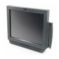
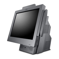
Installing the IBM AnyPlace Kiosk
Chapter 2. Installing the IBM AnyPlace Kiosk 13