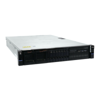
Figure 71. Upper and lower cable-management arms
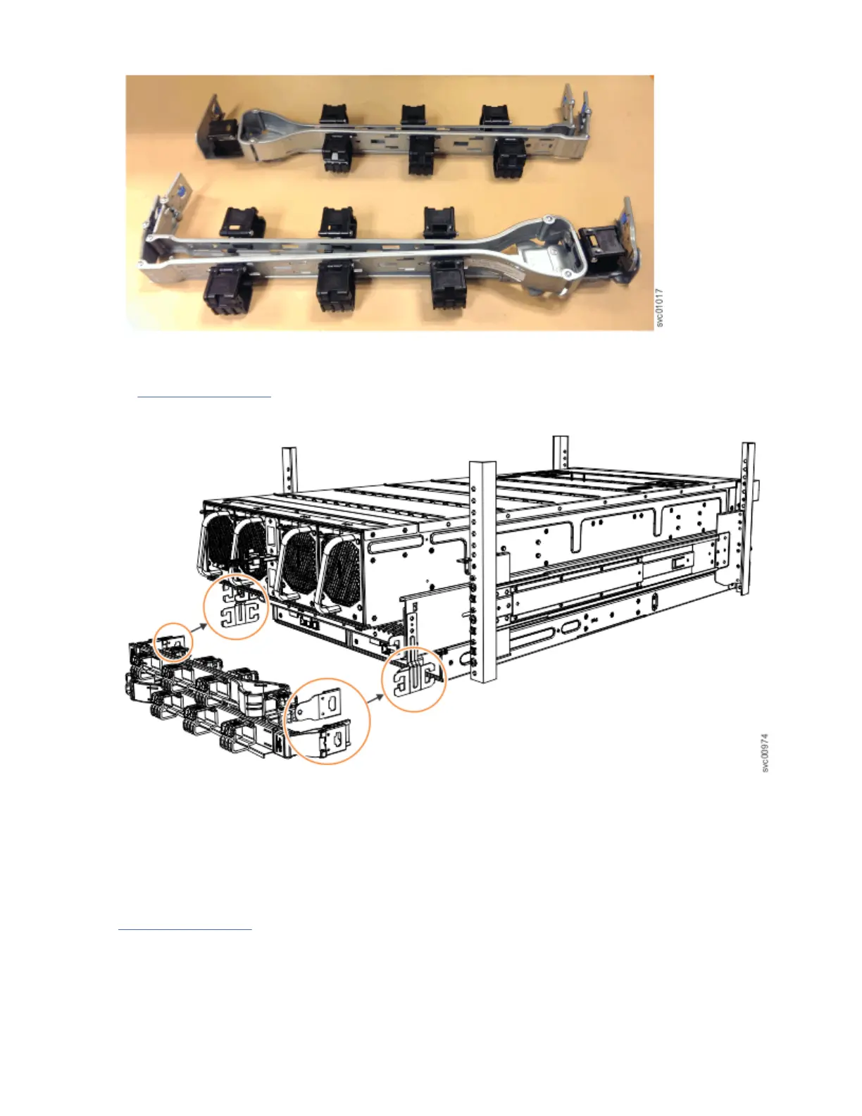
As Figure 72 on page 69 shows, the support rail connectors of each CMA assembly are installed on the
rail hooks at the end of the support rails.
Figure 72. Upper and lower cable-management arms
Procedure
1. Remove the loop straps from the upper and lower CMA assemblies. The straps are used only for
shipping.
Installing the upper CMA assembly
Figure 73 on page 70 shows the connectors on the upper CMA assembly.
Chapter 4. Installing an optional 5U SAS expansion enclosure
69
 Loading...