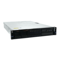
Figure 67. Upper and lower CMA assemblies moved aside
Figure 68 on page 67 shows that the lower CMA assembly is swung away from the rear of the enclosure
so that the expansion canister is accessible.
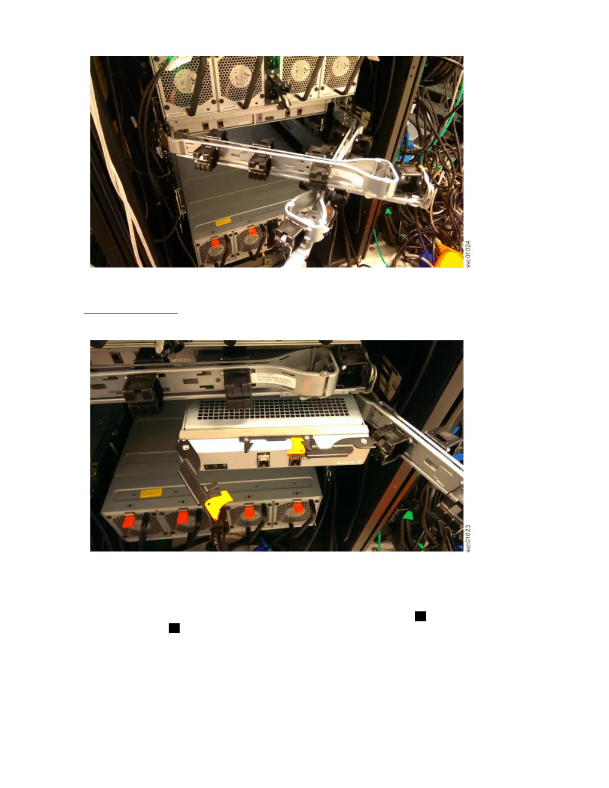
Figure 68. Lower CMA assembly moved
Procedure
1. To release the upper CMA, push the latch on the support rail connector 5 to release it from the
connector base 6 on the right rail.
Chapter 4. Installing an optional 5U SAS expansion enclosure
67
 Loading...