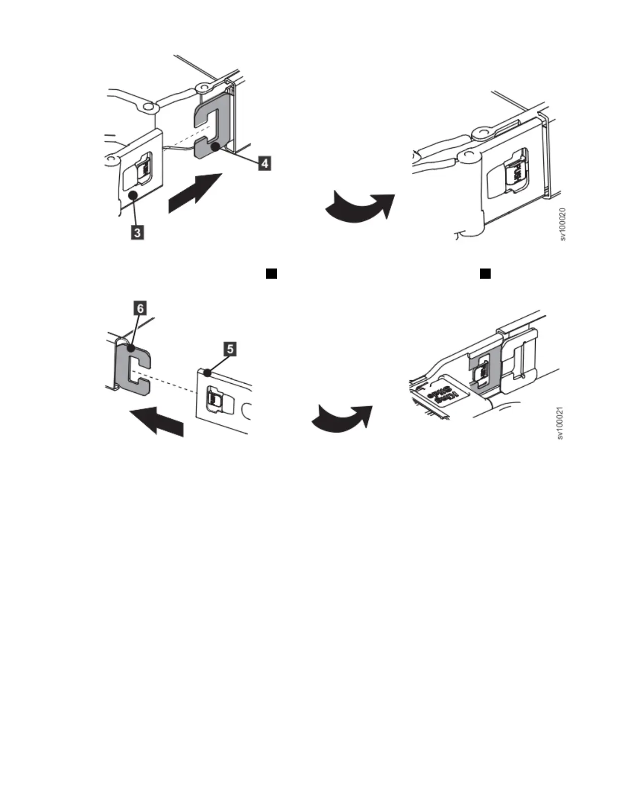
Figure 29. Install the outer member
4. Install the opposite CMA connector ( 5 ) to the opposite outer CMA connector base ( 6 ) as shown in
the following gure.
Figure 30. Install the other outer member
5. Connect and route the cables.
a) Connect the power cords and other cables to the rear of the node.
b) Route the cables and power cords on the CMA and secure them with cable ties or hook-and-loop
fasteners.
Note:
• The location of the cable straps can vary in different systems.
• Use the cable straps that are provided on the rear of the system to retain the cables and prevent
them from sagging.
• Allow slack in all cables to avoid tension in the cables as the CMA moves.
Connecting the SAN Volume Controller 2145-SV1 to the SAN and to the Ethernet network
Before you connect the SAN Volume Controller 2145-SV1 to the SAN, you must connect the Ethernet and
Fibre Channel cables.
Before you begin
Refer to the cable-connection table to nd out where to connect the Ethernet and Fibre Channel cables.
26
SAN Volume Controller : Model 2145-SV1 Hardware Installation Guide
 Loading...