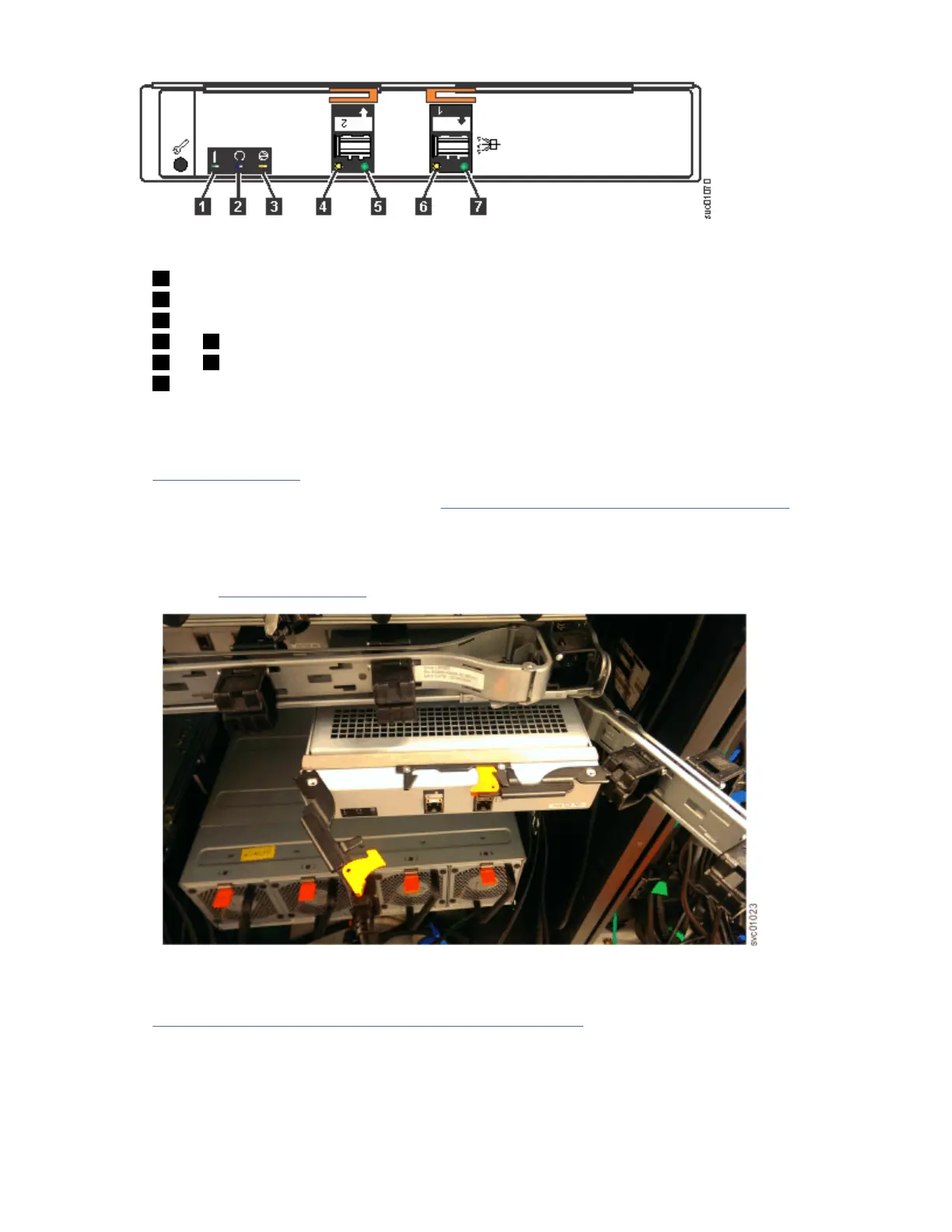
Figure 62. Expansion canister
1 Canister fault indicator
2 Canister status
3 Canister power indicator
4 and 6 SAS link fault indicators
5 and 7 SAS link operational indicators
8 Canister release handles
Procedure
1. Disconnect the elbow of the lower cable management arm to swing it out of the way, as shown in
Figure 63 on page 63.
Follow the procedure that is described in “Moving the cable management arms” on page 66.
2. Carefully align the expansion canister with the expansion enclosure.
3. Rotate both the handles outward and insert the expansion canister into the expansion enclosure.
4. When the expansion canister is fully inserted, rotate each handle inward to lock it into position, as
shown in Figure 63 on page 63.
Figure 63. Install the expansion canister
5. Reconnect all the SAS cables to the appropriate SAS ports on the expansion canister, as described in
“Removing and installing a SAS cable: 2145-92F ” on page 87.
6. Reconnect the elbow of the lower cable management arm to the inner member of the slide rail.
Chapter 4. Installing an optional 5U SAS expansion enclosure
63
 Loading...