About this task
The 2145-92F expansion enclosure supports 92 drives. Figure 81 on page 74 shows an example of a
drive assembly.
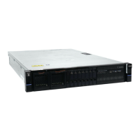
Figure 81. Drive assembly
1 Disk drive
2 Online indicator
3 Fault indicator
4 Release latch
5 Drive latch toes
6 Drive carrier
Procedure
1. Read all the available safety information.
2. Remove the cover, as described in “Removing the top cover: 2145-92F ” on page 56.
3. Locate the empty drive slot to receive the new drive or that contains the faulty drive that you want to
replace.
Note: When a drive is faulty, the amber fault indicator is lit ( 3 in Figure 81 on page 74). Do not
replace a drive unless the drive fault indicator is on or you are instructed to do so by a x procedure.
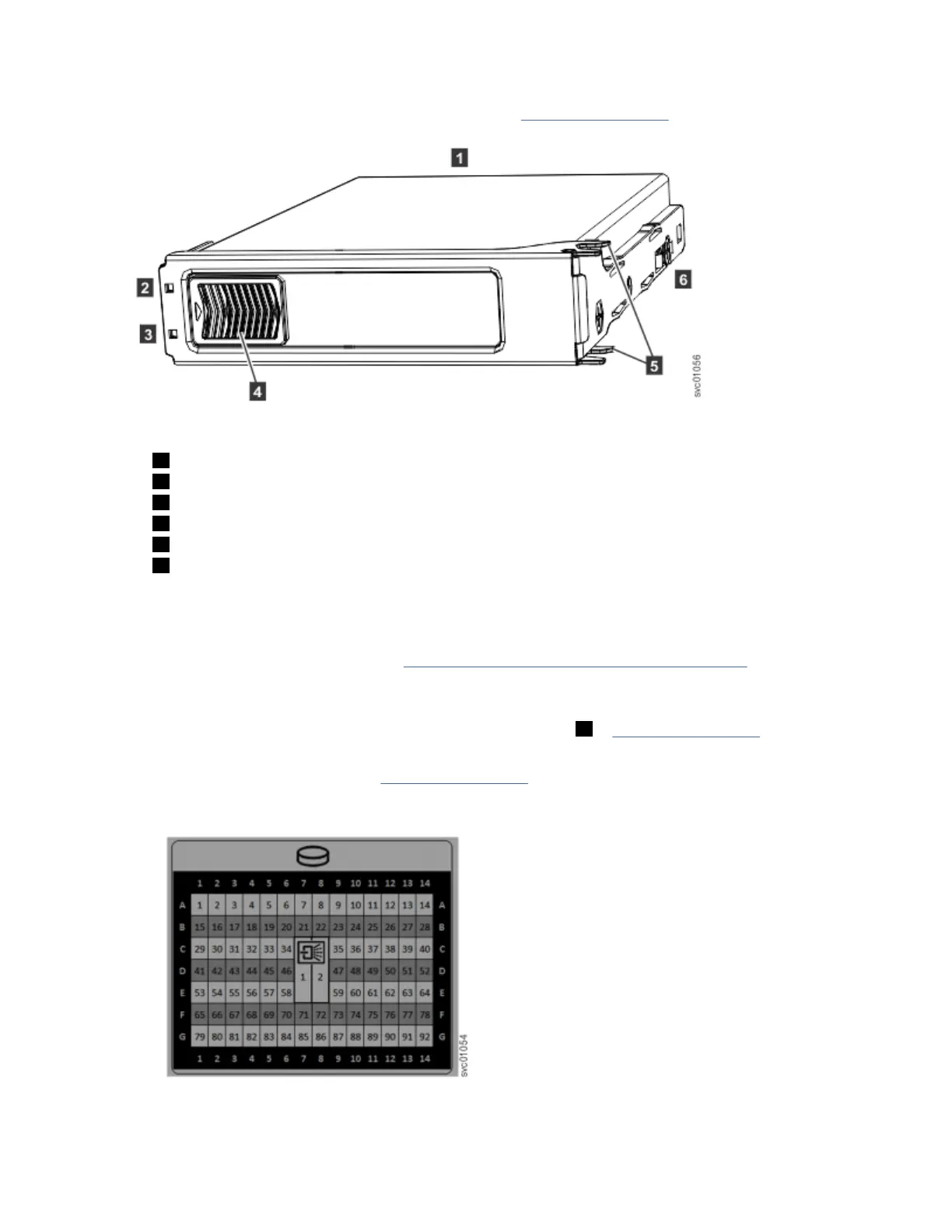
A label on the enclosure cover (Figure 82 on page 74) shows the drive locations in the enclosure.
The drive slots are numbered 1-14 from left to right and A-G from the back to the front of the
enclosure.
Figure 82. Drive locations in a 5U expansion enclosure
74
SAN Volume Controller : Model 2145-SV1 Hardware Installation Guide
 Loading...