6. Install the outer connector of the lower CMA assembly ( 9 ) to the outer member of the right support
rail 10 , as shown in Figure 77 on page 71.
7. Attach the support rail connector on the lower CMA assembly ( 11 ) to the connector on the left
support rail ( 12 ), as shown in Figure 77 on page 71.
Ensure that the lower CMA assembly is securely attached to the hooks on the end of the support rails.
8. Route the cables and power cords on the CMA. If needed, secure them with cable ties or hook-and-
loop fasteners.
Notes:
• Use the cable straps that are provided on the rear of the system to retain the cables and prevent
them from sagging.
• Allow slack in all of the cables to avoid tension in the cables as the CMA moves.
9. Reconnect the power cords and other cables, as needed.
Installing or replacing the top cover: 2145-92F
You can replace the top cover on a 2145-92F expansion enclosure during the installation process or after
you complete a service task.
Before you begin
Important: You can install the cover while the expansion enclosure is powered on. To maintain operating
temperature, replace the cover within 15 minutes of completing other service tasks. When the cover is
removed, the reduction in airflow through the enclosure might cause the enclosure or its components to
shut down to protect from overheating.
About this task
To install or replace the top cover on the 2145-92F expansion enclosure, complete the following steps.
Procedure
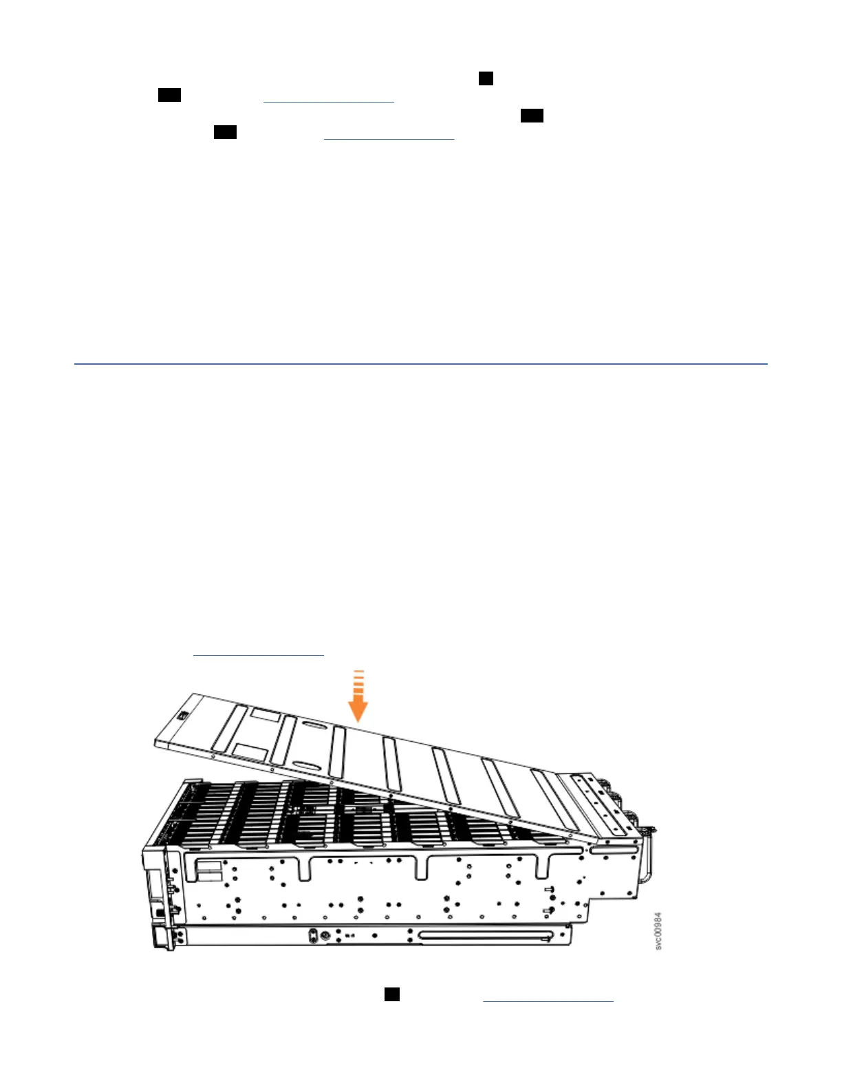
1. Carefully lower the cover and ensure that it is aligned correctly with the back of the enclosure, as
shown in Figure 78 on page 72
.
Figure 78. Aligning the 2145-92F top cover
2. Push the cover release lever to the side ( 2 ) as shown in Figure 79 on page 73.
72
SAN Volume Controller : Model 2145-SV1 Hardware Installation Guide
 Loading...