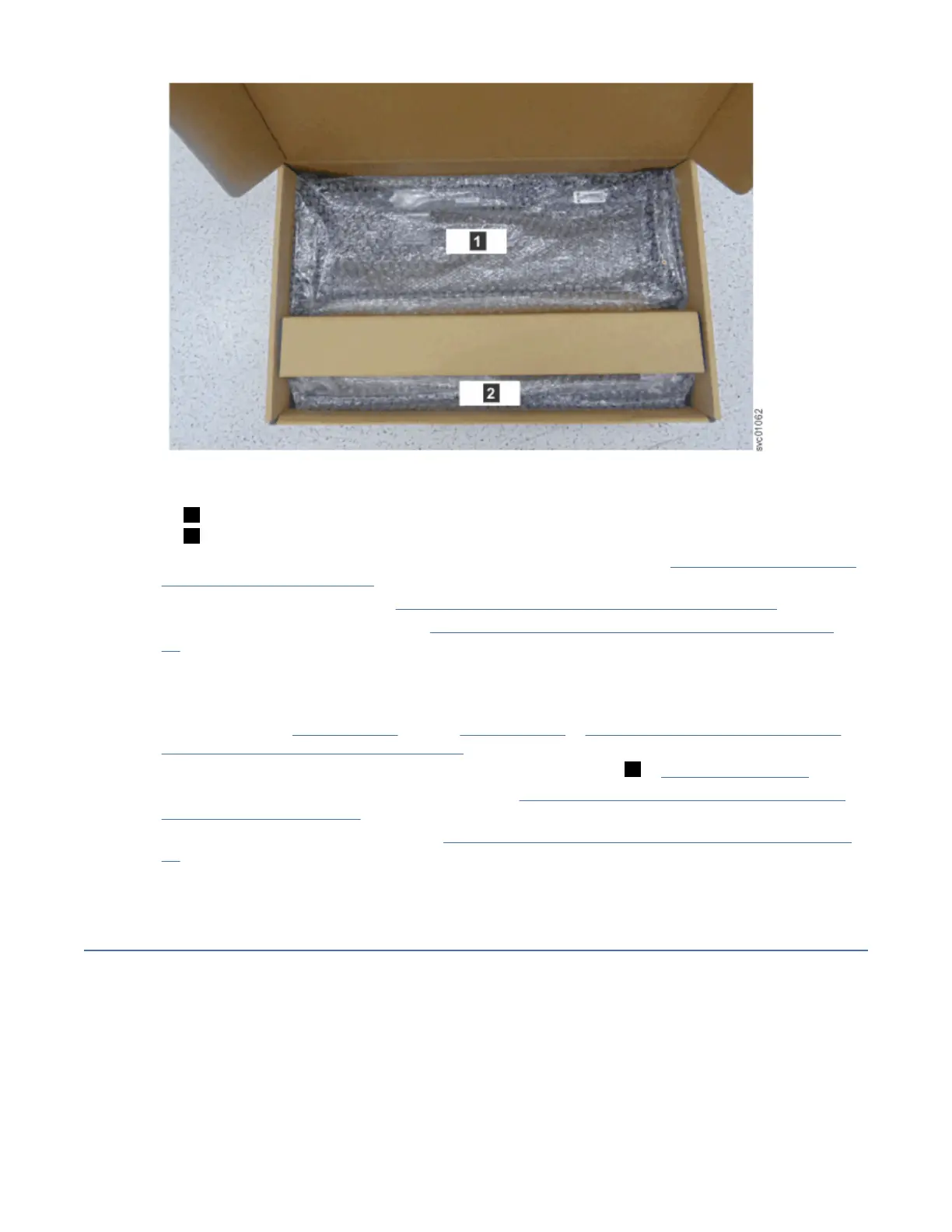
Figure 51. Packaging for fascia
1 4U fascia (front)
2 1U fascia (power supply units)
12. Attach the 4U and 1U fascia to the front of the enclosure, as described in “Installing or replacing the
fascia: 2145-92F ” on page 80.
13. Install the drives, as described in “Installing or replacing a drive: 2145-92F ” on page 73.
14. Replace the top cover, as described in “Installing or replacing the top cover: 2145-92F ” on page
72.
15. Lower the mechanical lift so that you can remove the remaining foam blocks away from the
expansion enclosure.
16. Slide the latch on the side of each rail and push the expansion enclosure securely into the rack, as
described in steps “3” on page 62 through “5” on page 62 in “Installing or replacing an expansion
enclosure in a rack: 2145-92F ” on page 61.
17. Remove the cable management arm assembly from its packaging ( 2 in Figure 49 on page 54).
18. Attach the cable management arm, as described in “Installing or replacing the cable-management
arm: 2145-92F ” on page 68.
19. Connect the SAS cables, as described in “Removing and installing a SAS cable: 2145-92F ” on page
87.
20. Connect the power cables.
Removing the top cover: 2145-92F
To complete some service tasks, you might need to remove the top cover from a 2145-92F expansion
enclosure.
Before you begin
Important: You can remove the cover without powering off the expansion enclosure. However, to
maintain operating temperature, replace the cover within 15 minutes of its removal. When the cover is
removed, the reduction in airflow through the enclosure might cause the enclosure or its components to
shut down to protect from overheating.
56
SAN Volume Controller : Model 2145-SV1 Hardware Installation Guide
 Loading...