8 Battery status LED
9 Operator-information panel
10 Front USB ports 1-3
11 Right side latch (releases chassis to slide out on rails)
12 Drive slot llers (no empty slots permitted)
13 Boot drives
14 Battery fault LED
15 Batteries
16 Left side latch (releases chassis to slide out on rails)
17 Machine type and model (MTM) and serial number
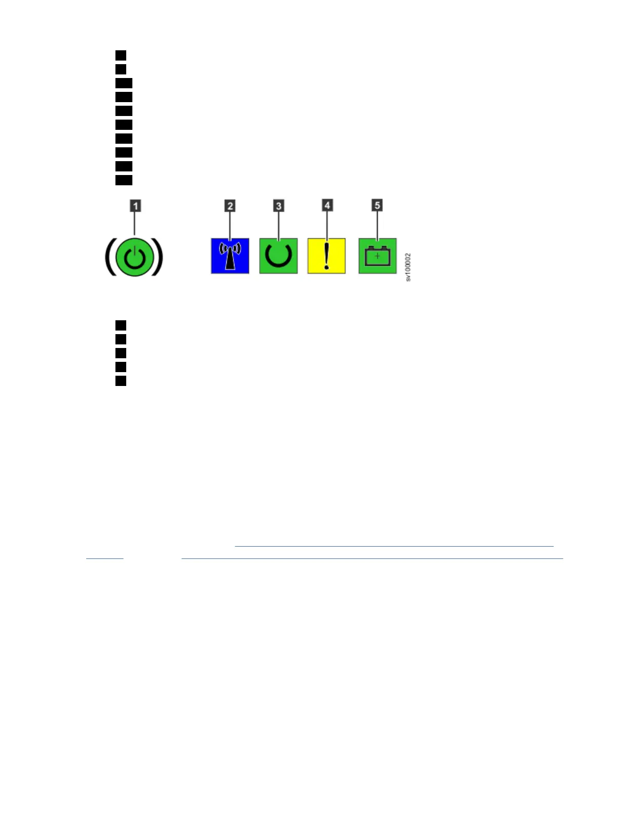
Figure 34. SAN Volume Controller 2145-SV1 operator-information panel
1 Power-control button and power-on LED
2 Identify LED
3 Node status LED
4 Node fault LED
5 Battery status LED
2. Verify that the node boots without error.
The Node status LED should slowly flash and the Node fault LED should be off. If the node fault LED is
lit, see the "Troubleshooting" section of the documentation. When the battery charge is low, the
battery status LED flashes. When the batteries are fully charged, the battery status LED is on. The
battery fault LEDs should be off.
Results
The installation of the SAN Volume Controller hardware is now complete. No software installation is
required.
What to do next
Continue with the instructions in“Installing the optional 2U SAS expansion enclosure into the rack” on
page 35 followed by Chapter 5, “Initializing the SAN Volume Controller 2145-SV1 system,” on page 137.
Chapter 2. Installing the SAN Volume Controller 2145-SV1 hardware
29
 Loading...