5. Attach the inner rail section to the new enclosure, as described in “Installing or replacing the support
rails: 2145-92F ” on page 57.
6. Replace the new enclosure in rack, as described in “Installing or replacing an expansion enclosure in
a rack: 2145-92F ” on page 61.
7. Reinstall the remaining parts into the enclosure, as described in the following topics. You can install
the parts in any order.
Important: Ensure that a mechanical lift is available and in place to support the additional weight as
the FRUs are reinstalled in the enclosure.
• “Installing or replacing a power supply: 2145-92F ” on page 82
• “Installing or replacing a drive: 2145-92F ” on page 73
• “Installing or replacing a secondary expander module: 2145-92F ” on page 77
• “Installing or replacing an expansion canister: 2145-92F ” on page 62
• “Installing or replacing a fan module: 2145-92F ” on page 90
• “Installing or replacing the top cover: 2145-92F ” on page 72
8. Reconnect the SAS cables, as described in “Connecting the optional 2145-92F SAS expansion
enclosures” on page 122 .
9. Reconnect the power cables, as described in “Powering on the 5U expansion enclosure: 2145-92F ”
on page 126.
10. Run the next recommended x procedure in the management GUI to set the serial number of the
2145-92F enclosure.
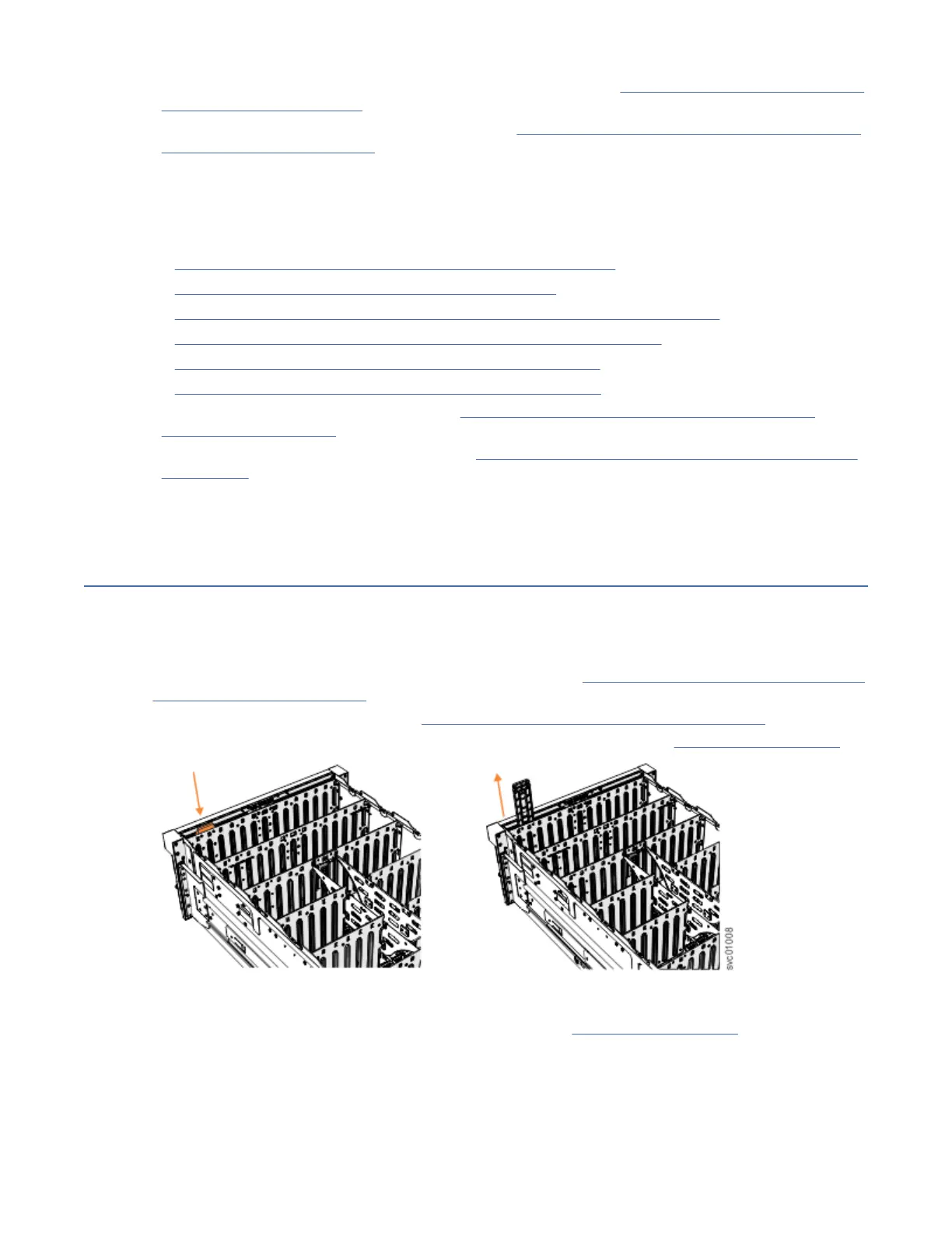
Removing the display panel assembly: 2145-92F
You can remove the display panel assembly from a 2145-92F expansion enclosure.
Procedure
1. Slide the expansion enclosure out of the rack, as described in “Removing an expansion enclosure from
a rack: 2145-92F ” on page 94.
2. Remove the top cover, as described in “Removing the top cover: 2145-92F ” on page 56.
3. Press the release tab at the top of the display panel assembly, as shown in Figure 128 on page 117.
Figure 128. Removing the display panel assembly
4. Carefully pull the display panel assembly, which is shown in Figure 129 on page 118, out of the
chassis.
Chapter 4. Installing an optional 5U SAS expansion enclosure
117
 Loading...