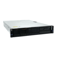
Figure 21. Identifying rack space
1 Front
2 Rear
3 Upper U (for 2U system)
4 Lower U
5 Location of optional screws for securing enclosure to rack
6 Location of rail-mounting pins
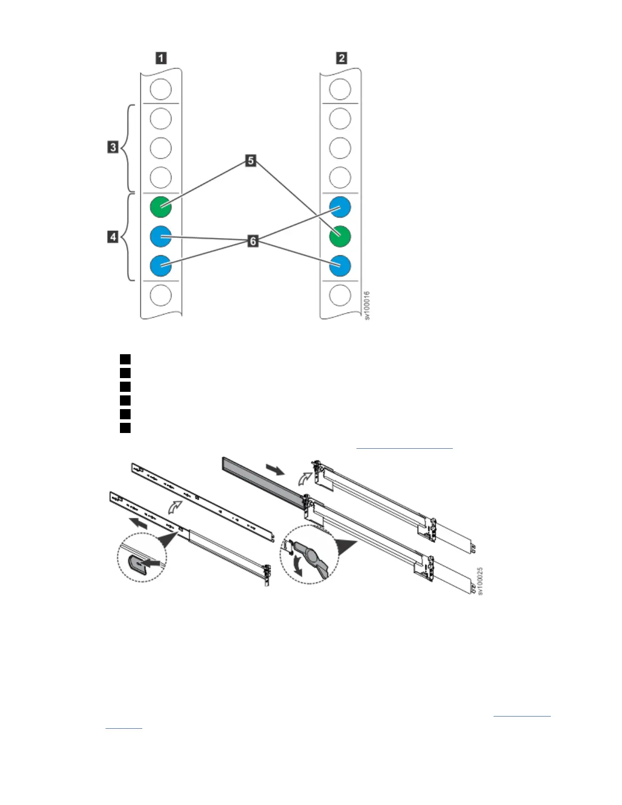
3. Detach the inner section of one 3-part rail, as shown in Figure 22 on page 21.
Figure 22. Detaching the inner rail section
a) Pull the tab forward.
b) Turn the rotation plate upward.
c) Slide the middle section back.
4. Install the inner section of the rail onto the chassis.
No screws are required. Fit the holes in the inner rail section over the heads of the pins on the side of
the appliance, then slide the rail toward the rear of the appliance to lock, as shown in Figure 23 on
page 22.
Chapter 2. Installing the SAN Volume Controller 2145-SV1 hardware
21
 Loading...