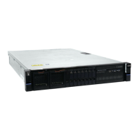
The drive slots must be populated sequentially, starting from the back-left corner position (slot 1,
grid A1). Sequentially install the drive in the slots from left to right and back row to front. Always
complete a full row before you install drives in the next row. For example, in Figure 83 on page 75,
the drives are installed correctly. Drives are installed in slots 1 -14 of row A and the installation
continues in slot 15 in row B.
Figure 83. Correct drive installation
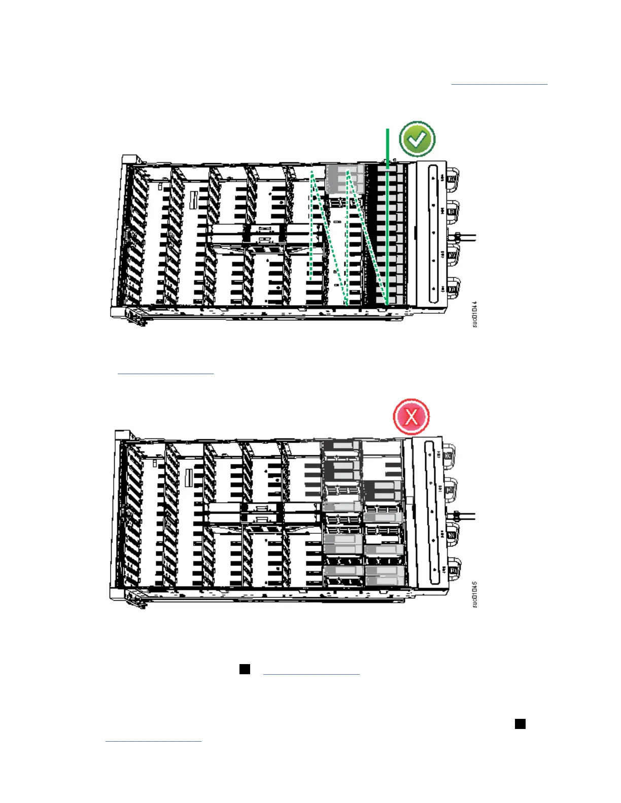
In Figure 84 on page 75, the drives are not installed correctly. Slot 1 (A1) does not contain a drive.
In addition, drives are installed in row B even though row A contains empty drive slots.
Figure 84. Incorrect drive installation
4. Touch the static-protective package that contains the drive to any unpainted metal surface on the
enclosure. Wear an anti-static wrist strap to remove the drive from the package.
5. Ensure that the drive handle ( 1 in Figure 85 on page 76) of the drive assembly is in the open
(unlocked) position.
6. Align the drive carrier into the appropriate drive slot.
7. Gently push the drive down until it stops and the bottom of the latch is aligned with the top of the
partition. Ensure that the handle is not open more than 45 degrees from the drive carrier. ( 2 in
Figure 85 on page 76).
Chapter 4. Installing an optional 5U SAS expansion enclosure
75
 Loading...