c. For other rail errors (Pwr rail 1 error, see step 4b), remove each component
that is associated with the faulty Pwr rail, one at a time, in the sequence
indicated in Table 22, restarting the server each time, until the cause of the
overcurrent condition is identified.
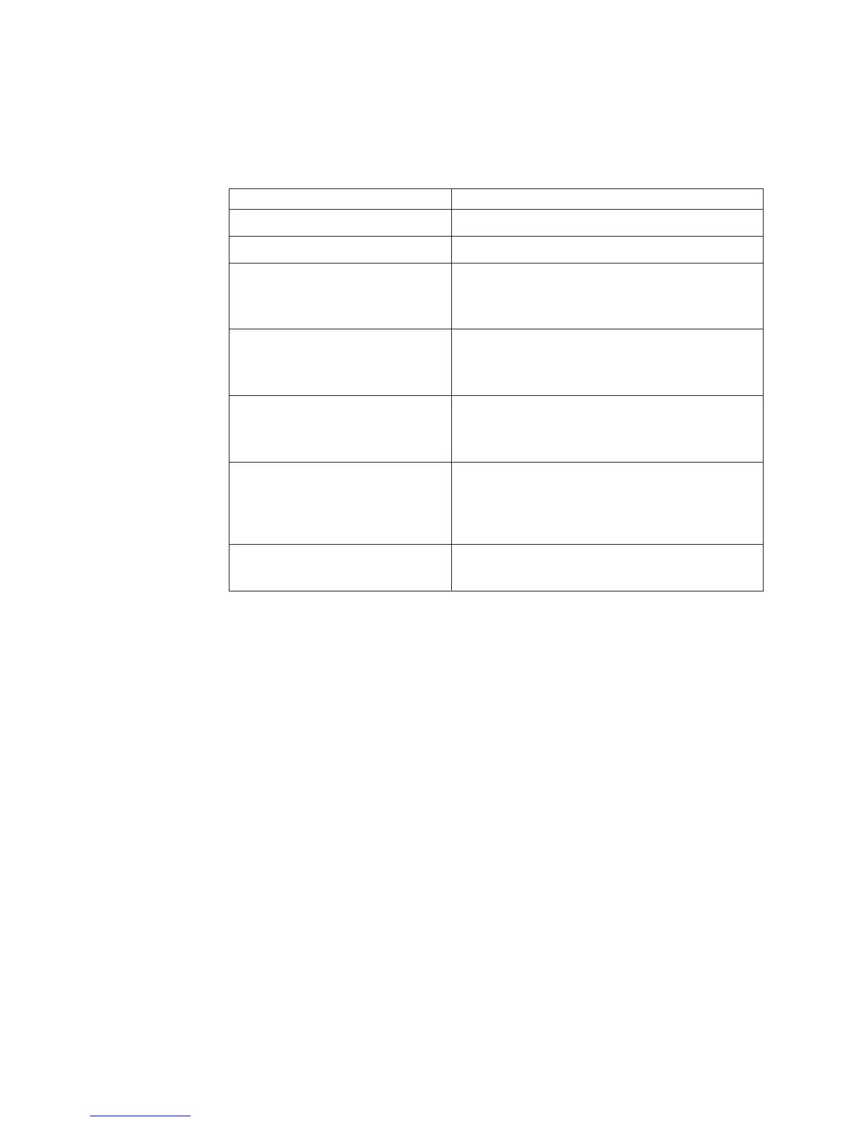
Table 22. Components associated with power rail errors
Pwr rail error in the IMM event log Components
Pwr rail 1 error
v Microprocessor 1
Pwr rail 2 error
v Microprocessor 2
Pwr rail 3 error
v DIMMs 1 through 12
v Fan 3
v Fan 4
Pwr rail 4 error
v Fan 5
v Fan 6
v DIMMs 13 through 24
Pwr rail 5 error
v Fan 7
v Fan 8
v SAS/SATA hard disk drives and USB
Pwr rail 6 error
v Optional cable for VGA external power
v PCI-E and x16 (maximum expansion is 4 adapter
cards
v PCI-E hard disk drives
Pwr rail 7 error
v Fan 1
v Fan 2
d. Replace the identified component.
5. Remove the adapters and disconnect the cables and power cords to all internal
and external devices until the server is at the minimum configuration that is
required for the server to start (see “Power-supply LEDs” on page 69 for the
minimum configuration).
6. Reconnect all power cords and turn on the server. If the server starts
successfully, reseat the adapters and devices one at a time until the problem is
isolated.
Results
If the server does not start from the minimum configuration, see “Power-supply
LEDs” on page 69 to replace the components in the minimum configuration one at
a time until the problem is isolated.
102 IBM System x3550 M5 Type 5463: Installation and Service Guide

 Loading...


