Server controls, LEDs, and power
This section describes the controls and light-emitting diodes (LEDs) and how to
turn the server on and off.
For the locations of other LEDs on the system board, see “System-board LEDs” on
page 30.
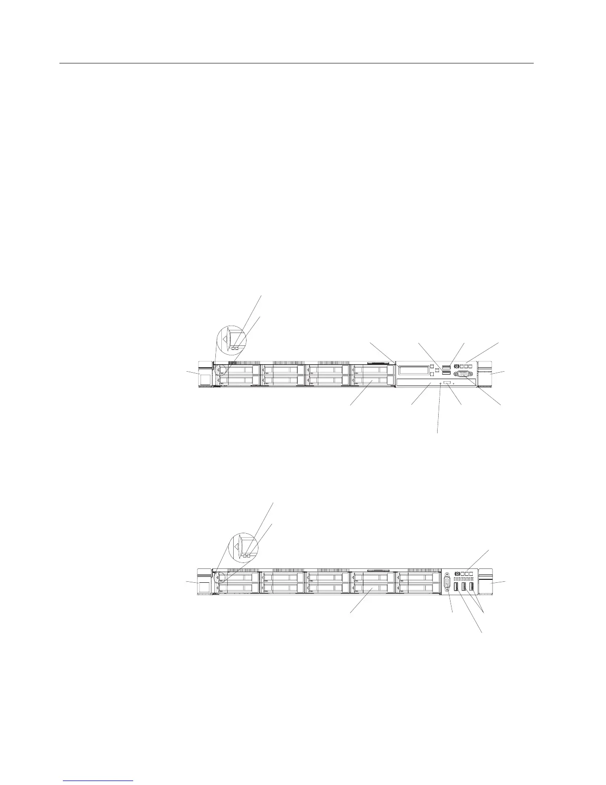
Front view
The following illustrations show the controls, LEDs, and connectors on the front of
your server model. As they are the same for either hot-swap or simple-swap
models, only the hot-swap model is used to show the relevant locations.
Note: The ten 2.5-inch simple-swap hard disk drive model is not supported.
Controls, LEDs, and connectors on your server model.
Hard disk drive
activity LED (green)
Hard disk drive
status LED (yellow)
DVD
optical
drive bay
DVD drive
activity LED
DVD drive
eject button
Video
connector
USB 3.0
connectors
Operator
information
panel
LCD system
information
display panel
2.5-inch hard disk
drive bays
Rack
release
latch
Rack
release
latch
USB 2.0
connectors
Figure 10. Front view: Eight 2.5-inch hot-swap hard disk drive bay model
Video
connector
USB 2.0
connectors
USB 3.0
connectors
Hard disk drive
activity LED (green)
Hard disk drive
status LED (yellow)
2.5-inch hard disk
drive bays
Operator
information
panel
Rack
release
latch
Rack
release
latch
Figure 11. Front view: Ten 2.5-inch hot-swap hard disk drive bay model
18 IBM System x3550 M5 Type 5463: Installation and Service Guide

 Loading...


