3. Carefully push the media cage back into the chassis (see “Replacing the media
cage” on page 224). Remember to reconnect the cables that were removed from
the system board.
4. Reinstall the cover (see “Replacing the cover” on page 127).
5. Slide the server into the rack.
6. Reconnect the power cords and any cables that you removed.
7. Turn on the peripheral devices and the server.
Removing the operator information panel assembly
Use this information to remove the operator information panel assembly.
About this task
To remove the operator information panel assembly, complete the following steps.
Procedure
1. Read the safety information that begins on “Safety” on page vii and
“Installation guidelines” on page 122.
2. Turn off the server and peripheral devices and disconnect all power cords;
then, remove the cover (see “Removing the cover” on page 126).
3. For the eight 2.5-inch hot-swap or simple-swap and ten 2.5-inch hot-swap hard
disk drive server configuration, remove the media cage (see “Removing the
media cage” on page 222). For the four 3.5-inch hot-swap or simple-swap hard
disk drive server configuration, disconnect the operator information panel
assembly cable from the system board; then, remove the assembly from the
chassis. See the following illustration when you have this particular server
model.
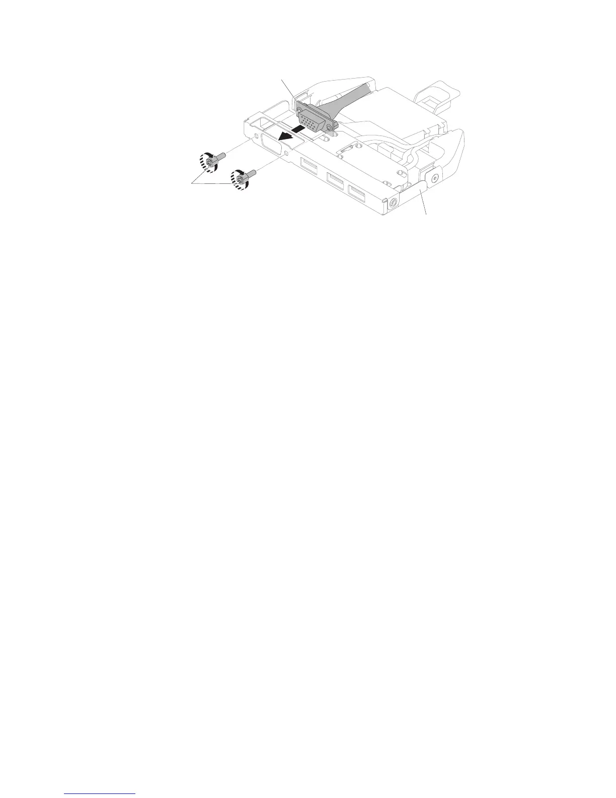
Media cage
Video connector
Screws
Figure 156. Front video connector assembly installation for four 3.5-inch hot-swap or
simple-swap hard disk drive server configuration
234 IBM System x3550 M5 Type 5463: Installation and Service Guide

 Loading...


