v PCI slot 1: Depending on the server configuration, insert a low-profile PCI
Express or a ML2 adapter into this slot.
v PCI slot 2: Depending on the server configuration, insert a half-length,
full-height PCI Express or a low-profile PCI Express adapter into this slot.
v PCI slot 3: Insert a low-profile PCI Express into this slot.
v Ethernet connectors: Use either of these connectors to connect the server to a
network.
v Systems-management Ethernet connector: Use this connector to connect the
server to a network for full systems-management information control. This
connector is used only by the integrated management module (IMM2.1). A
dedicated management network provides additional security by physically
separating the management network traffic from the production network. You
can use the Setup utility to configure the server to use a dedicated systems
management network or a shared network.
v USB connectors: Connect a USB device, such as a USB mouse or keyboard to
any of these connectors.
v NMI button: Press this button to force a nonmaskable interrupt to the
microprocessor. It allows you to blue screen the server and take a memory
dump (use this button only when directed by the IBM service support). You
might have to use a pen or the end of a straightened paper clip to press the
button. The NMI button is in the lower left-hand corner on the rear of the
server.
v Video connector: Connect a monitor to this connector. The video connectors on
the front and rear of the server can be used simultaneously.
Note: The maximum video resolution is 1600 x 1200 at 75 Hz.
v Power cord connector: Connect the power cord to this connector.
Note: Power supply 1 is the default/primary power supply. If power supply 1
fails, you must replace it immediately.
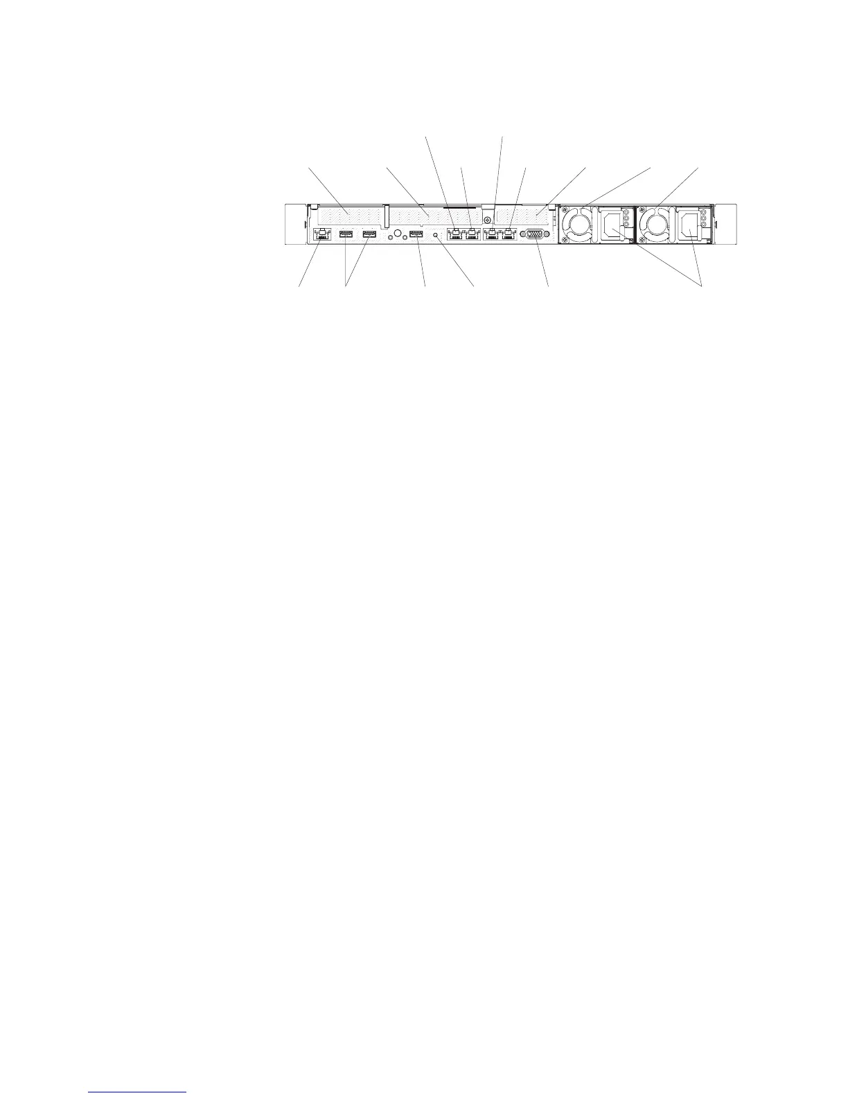
The following illustration shows the LEDs on the rear of the server.
USB 3.0
connectors
USB 2.0
connector
Video
connector
Power cord
connectors
Power
supply 1
Power
supply 2
Slot 3
PCI Express
(low-profile)
Slot 2
PCI Express
(full-height
half-length)
Slot 1
PCI Express
(ML2)
Ethernet
connector 4
Ethernet
connector 3
Ethernet
connector 2
Ethernet
connector 1
NMI
System management
(dedicated)
Figure 19. Rear view connector illustration when one ML2, one full-height half length and one
low-profile PCI riser card assembly is installed in the server.
24 IBM System x3550 M5 Type 5463: Installation and Service Guide
 Loading...


