Chapter 5. IBM BladeCenter HX5 179
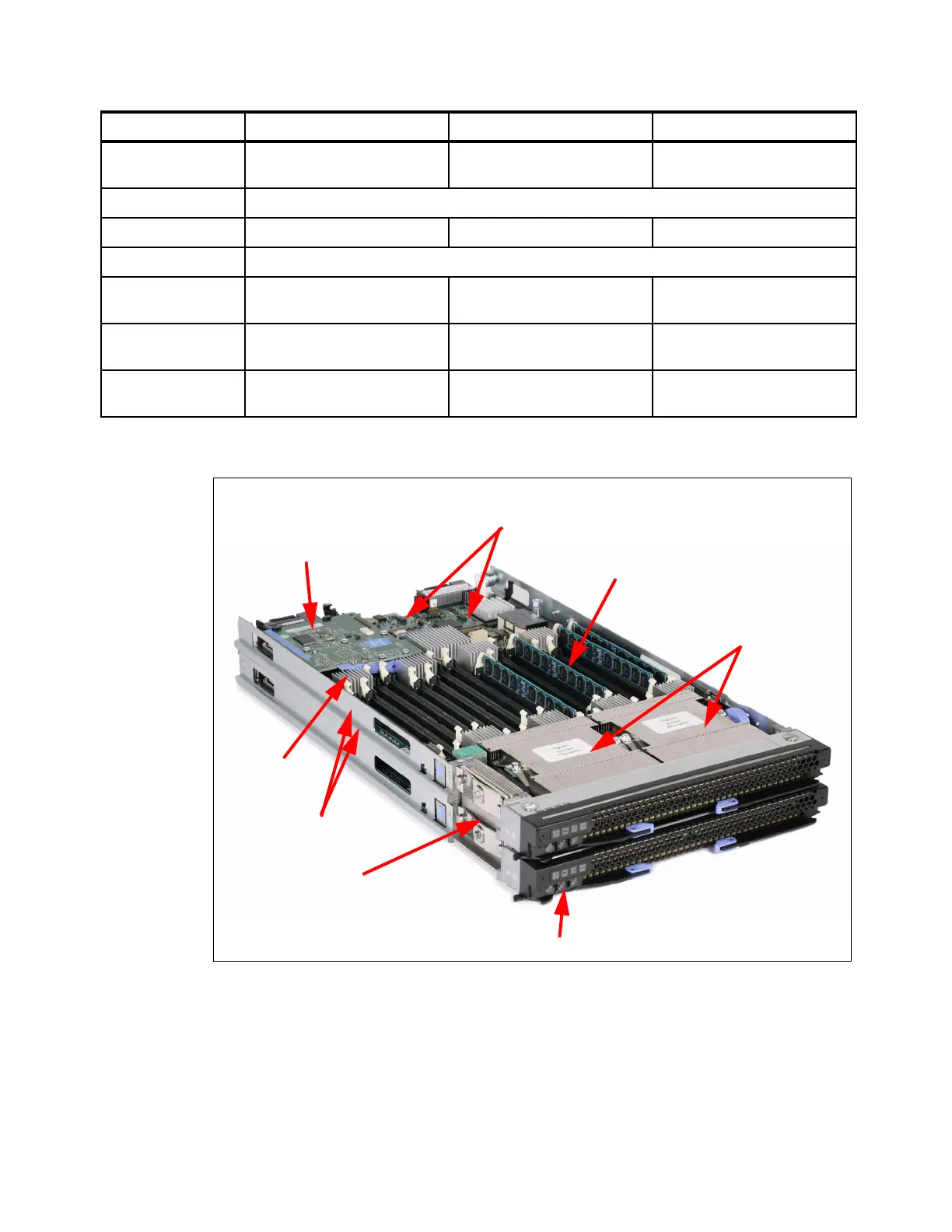
Figure 5-2 shows the components on the system board of the HX5.
Figure 5-2 Layout of HX5 (showing a 2-node 4-socket configuration)
The MAX5 memory expansion blade, which is shown in Figure 5-3 on page 180, is a device
with the same dimensions as the HX5. When the MAX5 is attached to the HX5, the combined
Maximum RAM
(using 8 GB DIMMs)
128 GB 256 GB 320 GB
Memory type DDR 3 error checking and correction (ECC) Very Low Profile (VLP) Registered DIMMs
DIMMs per channel 1 1 HX5: 1; MAX5: 2
Internal storage Optional 1.8-inch solid-state drives (SSDs); Non-hot-swap (require an additional SSD carrier)
Maximum number of
drives
Two Four Two
Maximum internal
storage
Up to 100 GB using two
50 GB SSDs
Up to 200 GB using four
50 GB SSDs
Up to 100 GB using two
50 GB SSDs
I/O expansion One CIOv
One CFFh
Two CIO v
Two CFF h
One CIOv
One CFFh
Features HX5 2-socket HX5 4-socket HX5 2-socket with MAX5
Intel Xeon
processors
Memory
Two 1.8-inch SSD
drives (under carrier)
Memory
Buffers
Two 30 mm
nodes
QPI wrap card
connector
CIOv and CFFh
Expansion slots
Information panel LEDs

 Loading...


