Chapter 5. IBM BladeCenter HX5 195
For optimal performance, populate all DIMM slots on the HX5 before filling the MAX5.
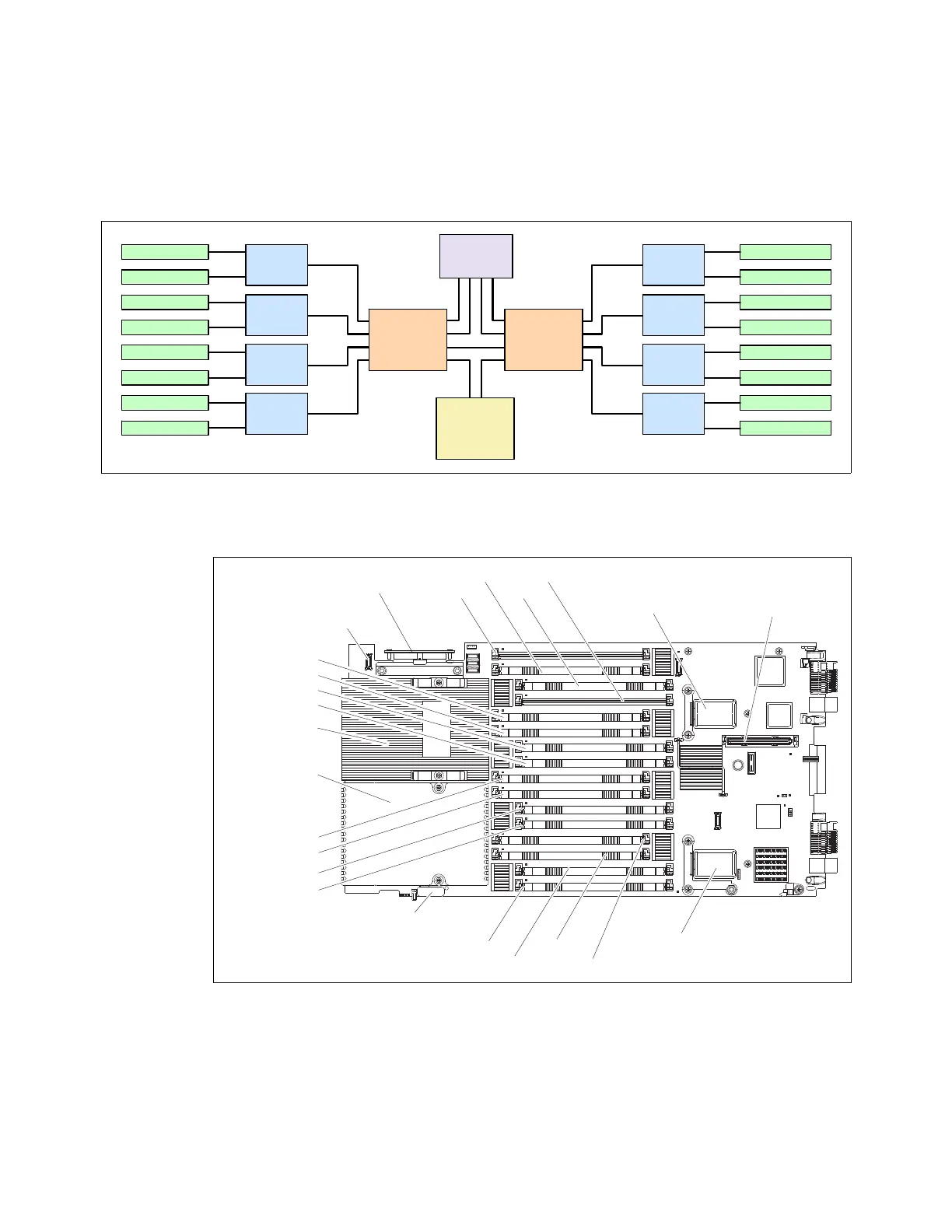
Each processor controls eight DIMMs and four memory buffers in the server, as shown in
Figure 5-12. To make use of all 16 DIMM sockets, you must install both processors. If only
one processor is installed, you can only install eight DIMM sockets.
Figure 5-12 Portion of the HX5 block diagram showing the processors, memory buffers, and DIMMs
Figure 5-13 shows the physical locations of the 16 memory DIMM sockets.
Figure 5-13 DIMM layout on the HX5 system board
The MAX5 memory expansion blade has 24 memory DIMM sockets, as shown in Figure 5-14
on page 196. The MAX5, which must be connected to an HX5 system (only the 1-node HX5
supports the MAX5), has one memory controller and six SMI-connected memory buffers.
DDR-3 DIMM 13
DDR-3 DIMM 14
DDR-3 DIMM 15
DDR-3 DIMM 16
DDR-3 DIMM 11
DDR-3 DIMM 12
DDR-3 DIMM 10
DDR-3 DIMM 9
Memory
buffer
Memory
buffer
Memory
buffer
Memory
buffer
Scalability
Connector
QPI Links
Intel 7500
I/O Hub
Intel Xeon
CPU 2
DDR-3 DIMM 5
DDR-3 DIMM 6
DDR-3 DIMM 7
DDR-3 DIMM 8
DDR-3 DIMM 3
DDR-3 DIMM 4
DDR-3 DIMM 2
DDR-3 DIMM 1
Memory
buffer
Memory
buffer
Memory
buffer
Memory
buffer
Intel Xeon
CPU 1
Memory
channels
SMI links
TIGHTEN
SCREWS
ALTERNATELY
Control panel
connector
Battery
DIMM 1
DIMM 2
DIMM 3
DIMM 4
DIMM 13
DIMM 14
DIMM 15
DIMM 16
Microprocessor 2
DIMM 9
DIMM 10
DIMM 11
DIMM 12
I/O expansion
connector
Blade expansion
connector
CIOv expansion
connector
DIMM 5
DIMM 6
DIMM 7
DIMM 8
Microprocessor 1
Scalability
connector

 Loading...


