Chapter 6. IBM System x3850 X5 and x3950 X5 237
There are four QPI cables connecting all of the QPI ports of both x3850 X5 servers.
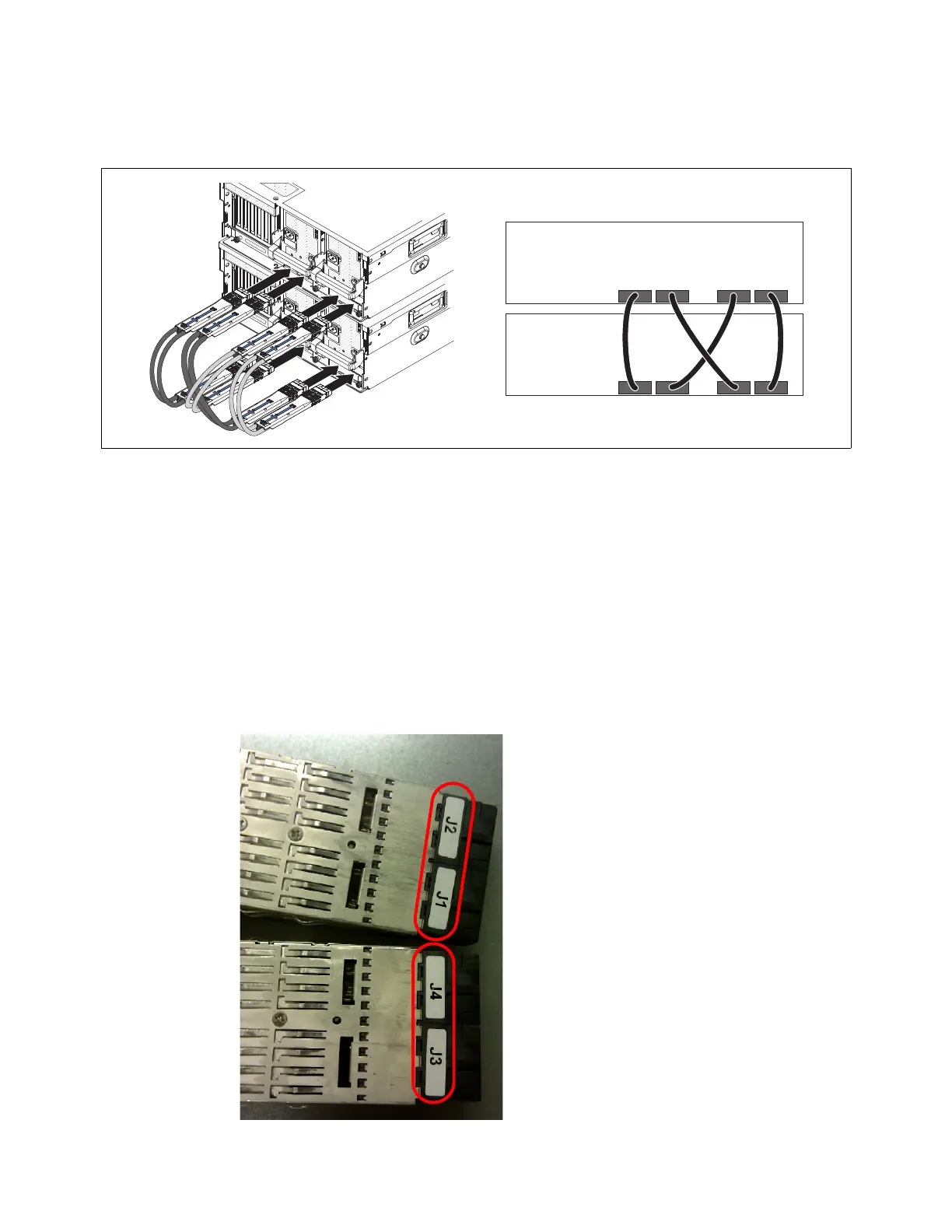
Figure 6-13 shows the cable routing.
Figure 6-13 Cabling diagram for 2-node x3850 X5
Consider this important information:
The QPI cables are keyed to be inserted only one way. A quick visual check for cable
orientation is to look for the blue retainer release tab on the top of each cable end. The
blue retainer release tab is placed on what becomes the visible top of the cable when the
cable is installed correctly.
The ends of the cable are labeled to indicate which end can be inserted into the correct
equipment. The server that becomes the primary node has the end of the QPI plugged
into it with the labels J2 and J1, as shown in Figure 6-14. The secondary node has the end
of the QPI cable plugged into it with the labels J4 and J3. All four QPI cables must be
oriented in the exact same manner. Neither server can power on if the cables are not
consistent in their orientation. Figure 6-14 shows how the cable ends are labeled.
Figure 6-14 QPI cable end labels: J1 and J2 attach to the primary node

 Loading...


