Chapter 7. IBM System x3690 X5 313
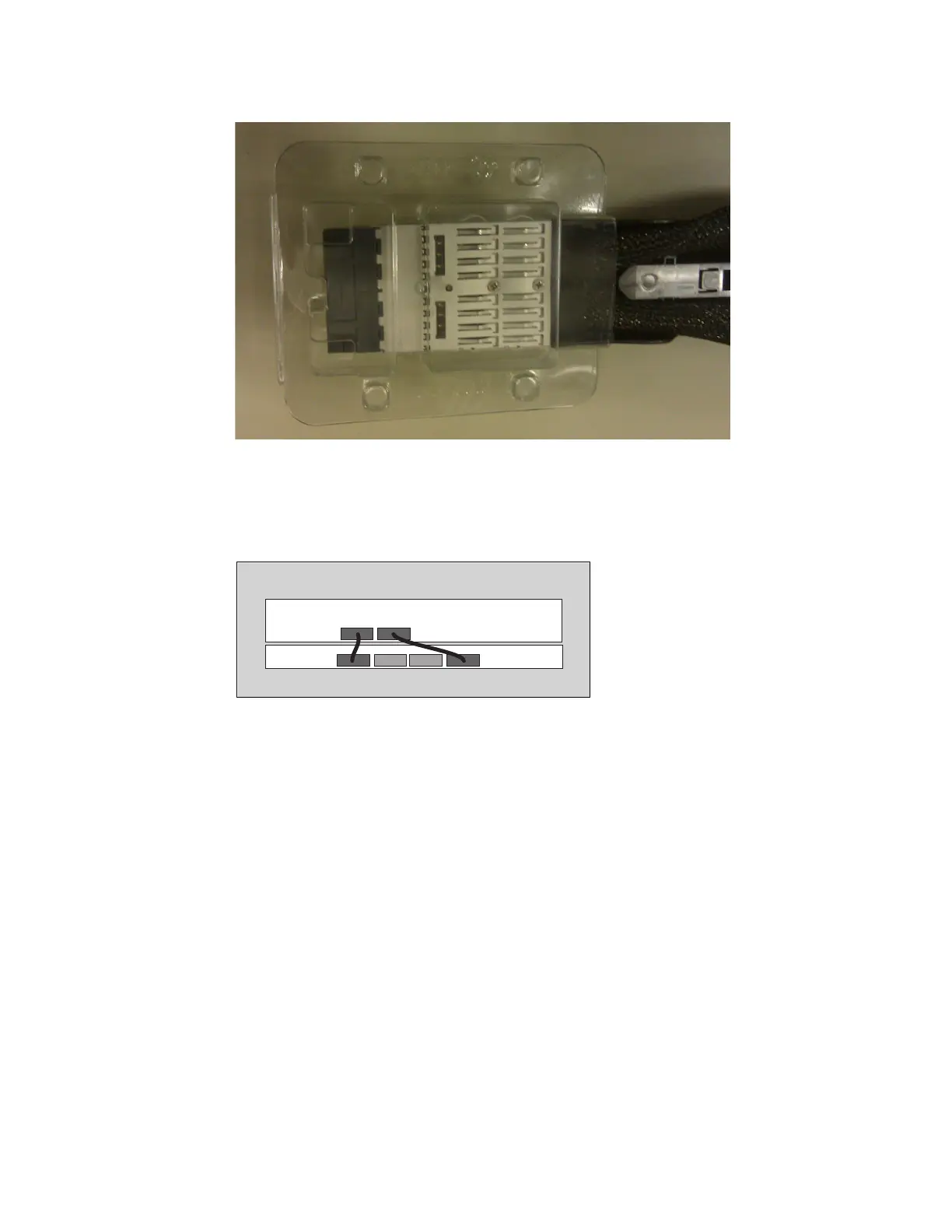
Figure 7-9 Reusable QPI cable connector protective boot
There are only two QPI cables connecting the two QPI ports of the x3690 X5 to two of the
four QPI ports on the MAX5. Figure 7-10 shows how the cables must be connected
between the QPI ports of the two units.
Figure 7-10 QPI cable installation
The QPI cables are keyed to only be inserted one way. A quick visual check for cable
orientation is to look for the 2U QPI or 1U QPI labels on the cable. The labels, along with
the blue retainer release tab, are placed on what will become the visible top of the cables
when they are installed correctly.
The ends of the cables are labeled to indicate which end to insert into the correct
equipment. The 2U QPI end of the cable plugs into the x3690 X5. The 1U QPI end of the
cable plugs into the MAX5.
The cable end must slide into the port until it clicks into place. You can disengage the
retainer that holds the cable in place by pressing on the blue tab on the top of the QPI
cable connection.
Both cables must be installed, even when only one processor is installed, to allow the
MAX5 to be controlled by the server. If one of the cables is detached, the server will not
power on or complete POST.

 Loading...


