18
Icon Name Function
Down/4
Assistant function such as PTZ
menu.
In text mode, input number 1/4
(English character G/H/I)
Left/2
Right/3
activated control,
jumping to
up/down/left/right.
When playback, click these
buttons to control playback bar.
In text mode, input number
2(English character A/B/C)
/3(English character D/E/F)
Power
Power button, press this button to boot up or shut
down NVR.
USB port
To connect USB storage device, USB mouse.
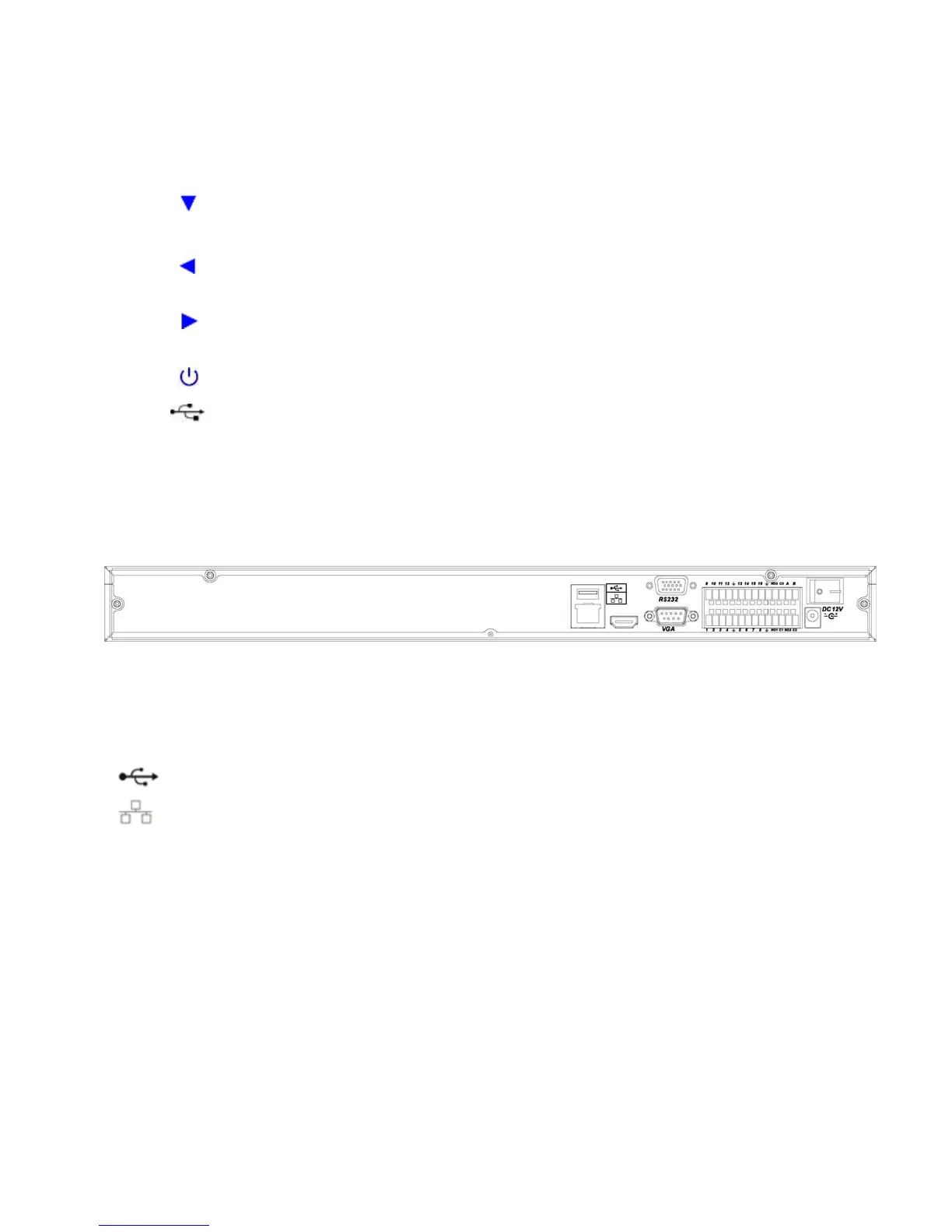
2.2 Rear Panel
2.2.1 A Series
The A series NVR real panel is shown as in Figure 2-4.
Figure 2-4
Please refer to the following sheet for detailed information.
Port Name Connection Function
USB port. Connect to USB mouse.
Network port 10M/100M self-adaptive Ethernet port. Connect
to the network cable.
RS232 232 debug
COM.
It is for general COM debug to configure IP
address or transfer transparent COM data.
VGA VGA video
output port
VGA VGA video output port. Output analog video
signal. It can connect to the monitor to view
analog video.
1~16
Alarm input port.
1~16
I/O port
z Four groups of alarm input ports. The first
group is from port 1 to port 4, the second
group is from port 5 to port 8, the third
group is from 9 to 12, and the fourth group
is from 13 to 16. They are to receive the
signal from the external alarm source.
There are two types; NO (normal