93
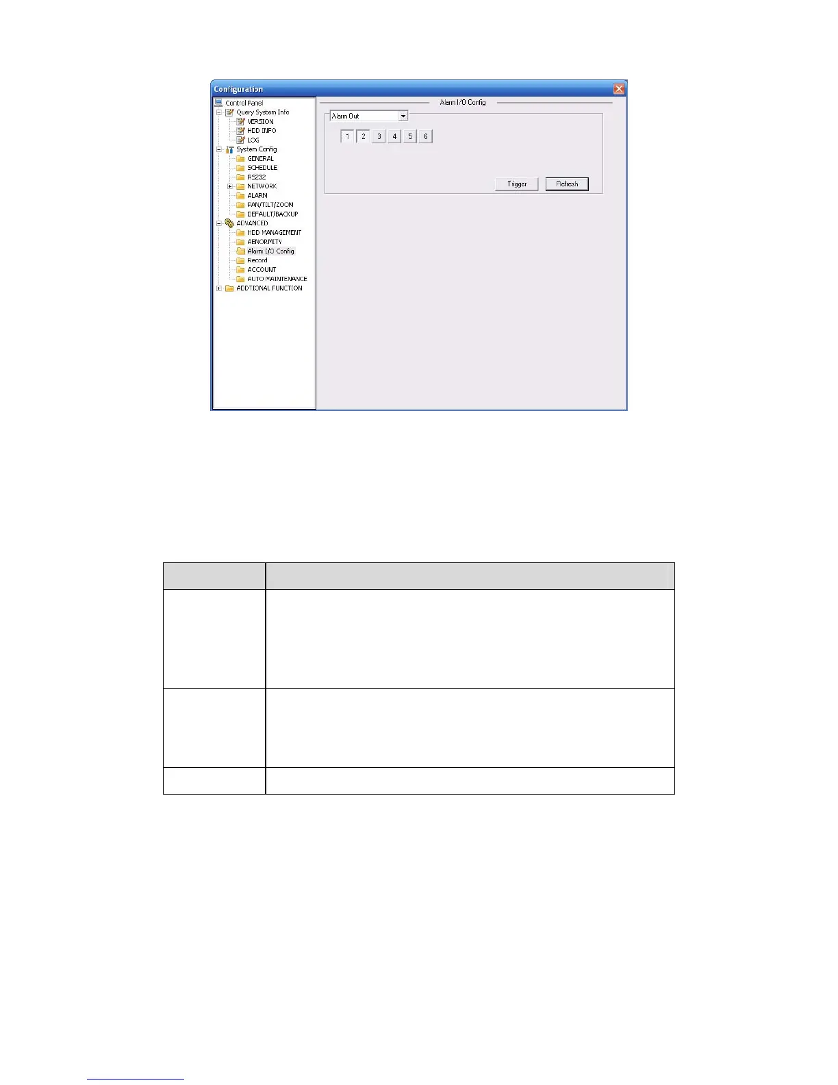
Figure 7-37 Alarm I/O Configuration
Important
The alarm output port should not be connected to high power load directly (It shall be less than
1A) to avoid high current which may result in relay damage. Please use the co contactor to
realize the connection between the alarm output port and the load.
Please refer to the following sheet for detailed information.
Parameter Function
Alarm output For A series product, there are three channels.
For L and S series product, there are six channels. The 6
th
channel is the controllable +12V alarm output.
Please click the corresponding number and then click the trigger
button.
Trigger Enable/disable alarm output.
Please note once you activate an alarm manually, you need to
click the output channel number again and then click trigger
button to disable it. Otherwise the alarm can not be cancelled.
Refresh
Search alarm output status.
7.3.3.3 Record
Record control interface is shown as in 334HFigure 7-38.