1-5
@5 MULTIFUNCTION SWITCHES
Push to select the functions indicated in the LCD
display to the right of these switches.
• Functions vary depending on the operating condition.
➥
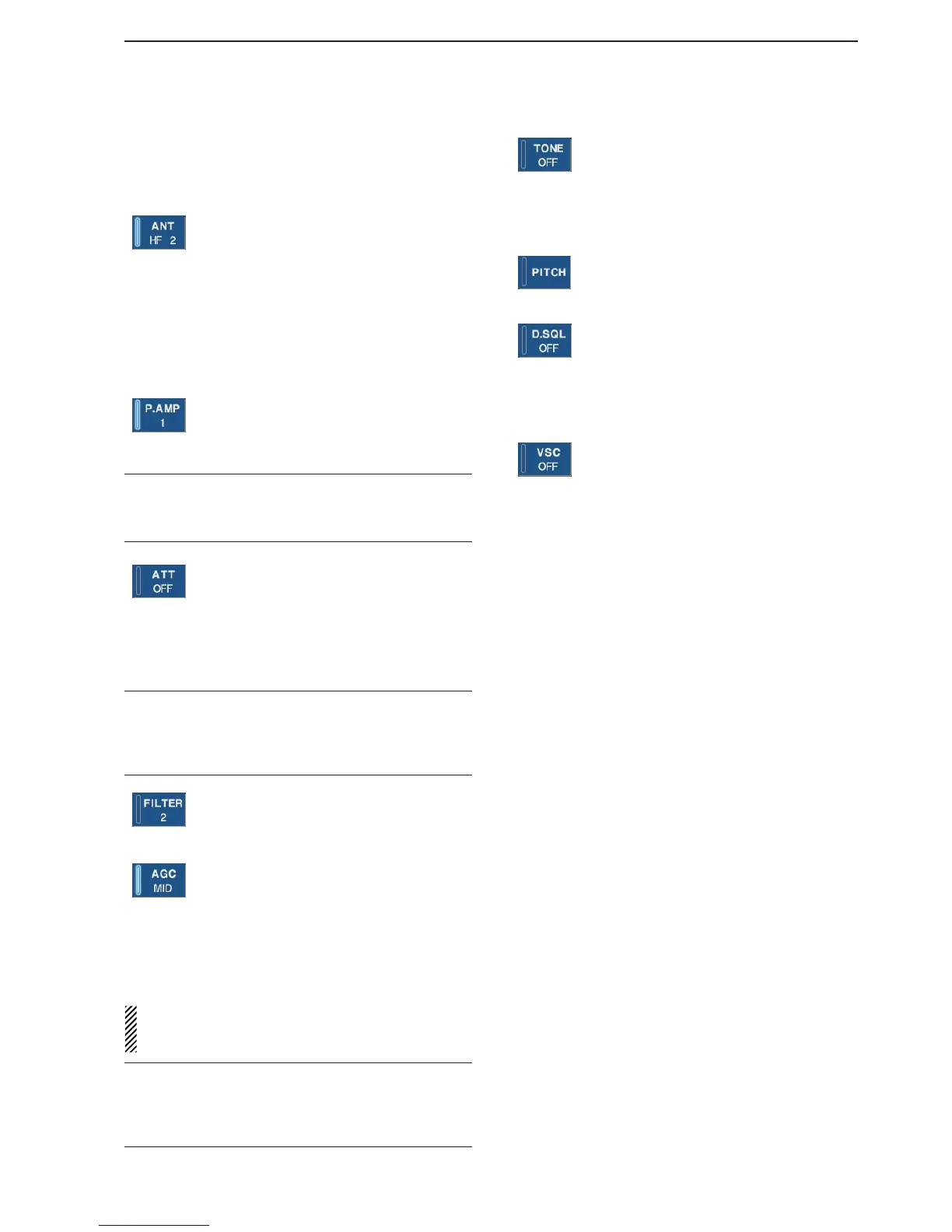
While operating HF bands, selects the an-
tenna connector from HF ANT 1, HF ANT
2 and HF ANT 3 when pushed. (p. 9-3)
• During 30–1150 MHz operation, only ANT 1
is available.
• During 1150–3335 MHz operation, only ANT
2 is available.
➥
Turns the antenna control voltage ON and
OFF form [ANT SEL] when pushed and
held for 1 sec. (p. 9-3)
➥ Selects one of 2 receive RF preamps or
bypasses them. (p. 5-9)
•“P. AMP1” activates 10 dB preamp.
•
“P. AMP2” activates 16 dB high-gain preamp.
✔
What is the preamp?
The preamp amplifies received signals in the front end cir-
cuit to improve S/N ratio and sensitivity. Select “P. AMP1” or
“P. AMP2” when receiving weak signals.
➥ Selects the attenuator when pushed.
(p. 5-9)
• HF bands: 6, 12, 18, 24, 30 dB.
• 30–1150 MHz,: 10, 20, 30 dB.
•1150–3335 MHz: 20 dB only.
➥ Turns OFF the attenuator when pushed
and held for 1 sec. (p. 5-9)
✔
What is the attenuator?
The attenuator prevents a desired signal from distorting
when very strong signals are near the receiving frequency,
or when very strong electric fields, such as from a broad-
casting station, are near your location.
➥ Selects one of 3 IF filter settings.
➥ Enters the filter set screen when pushed
and held for 1 sec.
➥
Activates and selects fast, middle or slow
AGC time constant when pushed. (p. 5-10)
• In FM/WFM or P25 mode, only “FAST” is
available.
• “VR (volume)” indicates that AGC time con-
stant depends on [AGC] control.
➥ Enters the AGC set mode when pushed
and held for 1 sec. (p. 5-10)
AGC time constant can be set from 0.1 to 8.0 sec.
(depends on mode)
, or turned OFF. When AGC is
“OFF,” the S-meter does not function.
✔
What is the AGC?
The AGC controls receiver gain to produce a constant audio
output level, even when the received signal strength varies
dramatically. Select “FAST” for tuning and then select “MID”
or “SLOW” depending on the receiving conditions.
➥
Switches between the tone squelch,
DTCS squelch function and no-tone oper-
ation when pushed in FM mode. (p. 4-4)
➥ Enters the tone set mode when pushed
and held for 1 sec. in FM/FSK mode.
(pgs. 4-4, 4-16)
➥
Push to toggle the CW pitch setting
screen ON and OFF in CW mode.
(p.4-10)
(Requires optional UT-122)
➥
Switches the digital squelch between
NAC squelch, selective squelch and OFF
in P25 mode. (p. 4-19)
➥
Enters the code set mode when pushed
and held for 1 sec. in P25 mode. (p. 4-19)
➥ Push to switch the voice squelch control
function ON and OFF; useful for scan-
ning.
@6 LCD FUNCTION DISPLAY (p. 1-10)
Shows the operating frequency, function switch
menus, spectrum scope screen, memory channel
screen, set mode settings, etc.
@7 RECEIVE INDICATOR [RECEIVE]
Lights green while receiving a signal and when the
squelch is open.
@8 REMOTE CONTROL INDICATOR [REMOTE]
Lights yellow when a command is received from a
PC via CI-V data.
• When this indicator lights yellow, all dials, keys or
switches other than [LOCAL] are disabled.
• This indicator goes OFF, when [LOCAL] is pushed.
@9 DIAL LOCK INDICATOR [LOCK] (p. 9-2)
Lights orange when the dial lock function is acti-
vated.
#0 LCD FUNCTION SWITCHES [F-1]–[F-7]
Push to select the function indicated in the LCD dis-
play above these switches.
• Functions vary depending on the operating condition.
#1 MINI SPECTRUM SCOPE SWITCH [M.SCOPE]
(p. 5-6)
Turns the mini spectrum scope screen ON or OFF.
• The mini spectrum scope screen can be displayed with
another screen, such as memory or set mode screen,
simultaneously.
#2 DISPLAY SWITCH [DISPLAY]
➥ Push to toggle the external input screen between
mini TV screen, full TV screen, or OFF.
• If no signal inputs from [VIDEO IN], black screen ap-
pears.
➥ Enter the display set mode menu screen when
pushed and held for 1 sec.
1
PANEL DESCRIPTION
 Loading...