FC6A S
ERIES
MICROS
MART
L
ADDER
P
ROGRAMMING
M
ANUAL
FC9Y-B1726 4-13
4: B
ASIC
I
NSTRUCTIONS
CDP (Dual-Pulse Reversible Counter)
The dual-pulse reversible counter CDP has up and down pulse inputs, so the three inputs are required. The circuit for a dual-pulse
reversible counter must be programmed in the following order: preset input, up-pulse input, down-pulse input, the CDP
instruction, and a counter number C0 through C511, followed by a counter preset value from 0 to 65,535.
The preset value can be designated using a decimal constant or a data register. When a data register is used, the data of the data
register becomes the preset value.
• The preset input must be turned on initially so that the current value returns to the preset value.
• The preset input must be turned off before counting may begin.
• After the current value reaches 0 (counting down), it changes to 65,535 on the next count down.
• After the current value reaches 65,535 (counting up), it changes to 0 on the next up count.
• The counter output is on only when the current value is 0.
• When the up pulse and down pulses are on simultaneously, no pulse is counted.
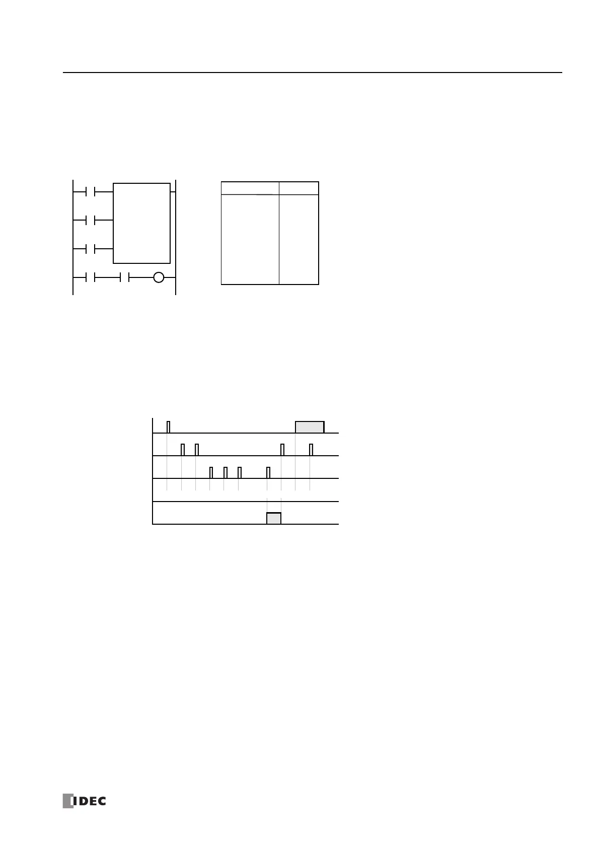
Ladder Diagram
I0
I1
CDP C1
500
I2
Preset Input
Up Pulse
Down Pulse
I3 C1 Q1
LOD
LOD
LOD
CDP
LOD
AND
OUT
I0
I1
I2
C1
500
I3
C1
Q1
Instruction Data
Program List
500 500
Preset Input I0
ON
OFF
Up Pulse I1
ON
OFF
Down Pulse I2
ON
OFF
Timing Chart
Counter C1
ON
OFF
500 501 502 501
Counter C1 Value
500 499 0 1
• • •
• • •

 Loading...