18: P
ULSE
O
UTPUT
I
NSTRUCTIONS
18-12 FC6A S
ERIES
MICROS
MART
L
ADDER
P
ROGRAMMING
M
ANUAL
FC9Y-B1726
Examples: PWM
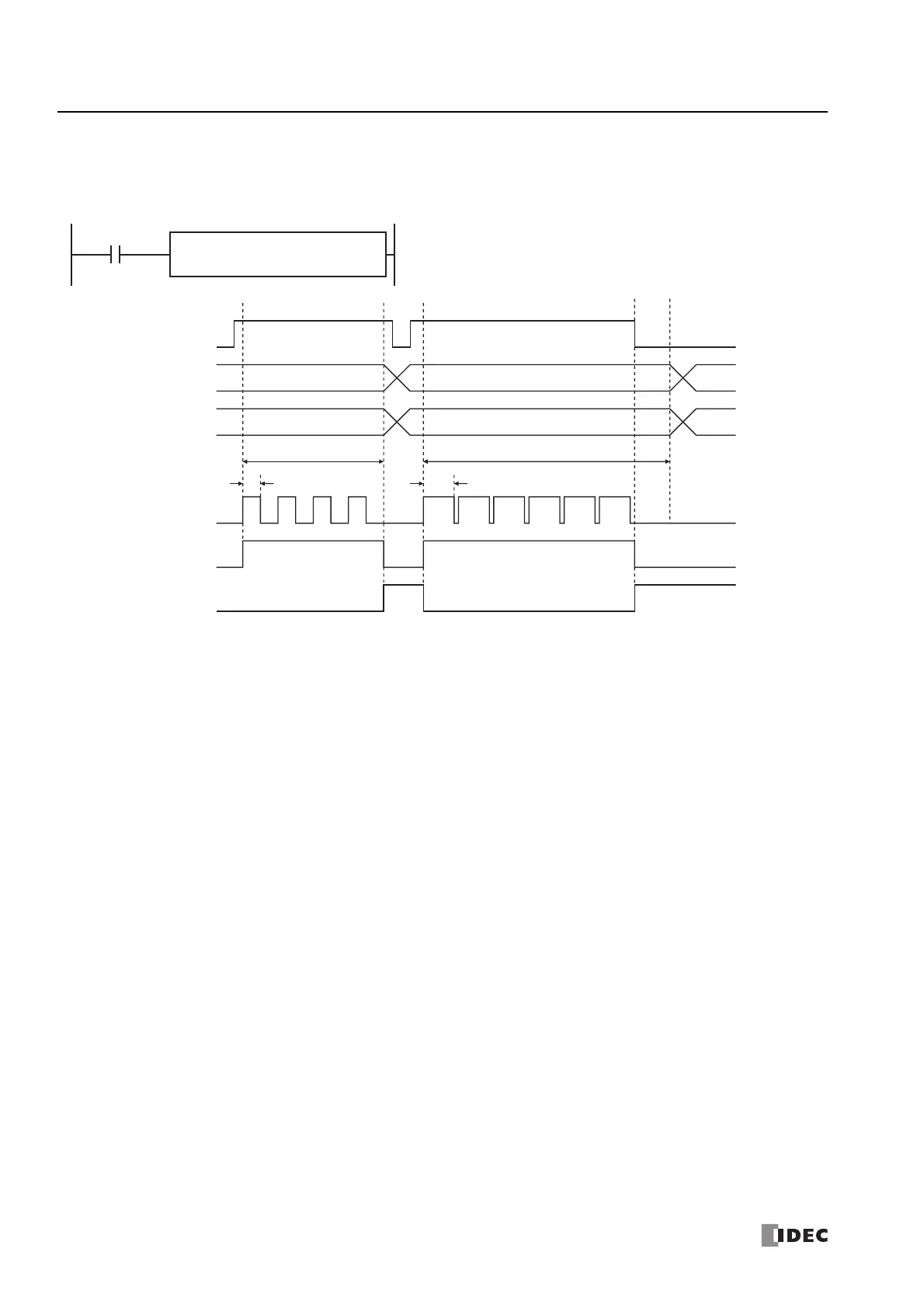
PWM1 instruction (pulse counting enabled) timing chart
[PWM1 instruction, S1 is specified as D200, D1 is specified as internal relay M0050]
When the PWM1 instruction input changes from off to on, M0050 turns on and pulses with the width ratio configured by D0201 are
output. When the number of pulses configured by D0202 and D0203 are output, pulse output stops. If the value of D0201 changes
during pulse output, pulses are output with the width ratio based on that value.
When the PWM1 instruction input changes from on to off, M0050 turns off and M0051 turns on at the same time.
The changes from the initialization input are not reflected while the PWM1 instruction input is on. If you wish to initialize the data
registers with the initialization input, turn the initialization input on after turning off the input.
D1
M0050
S2
M0000
PWM
1
S1
D0200
PWM1 instruction
input
PWM1 instruction input
Pulse width ratio D0201
Preset value
D0202, D0203
w1 w2 w3
n1 n2 n3
n1
w1
Output pulse Q0
n2
Pulse output ON M0050
Pulse output complete M0051
w1, w2, w3 = pulse width ratio
n1, n2, n3 = output pulse count
w2

 Loading...