FC6A S
ERIES
MICROS
MART
L
ADDER
P
ROGRAMMING
M
ANUAL
FC9Y-B1726 18-25
18: P
ULSE
O
UTPUT
I
NSTRUCTIONS
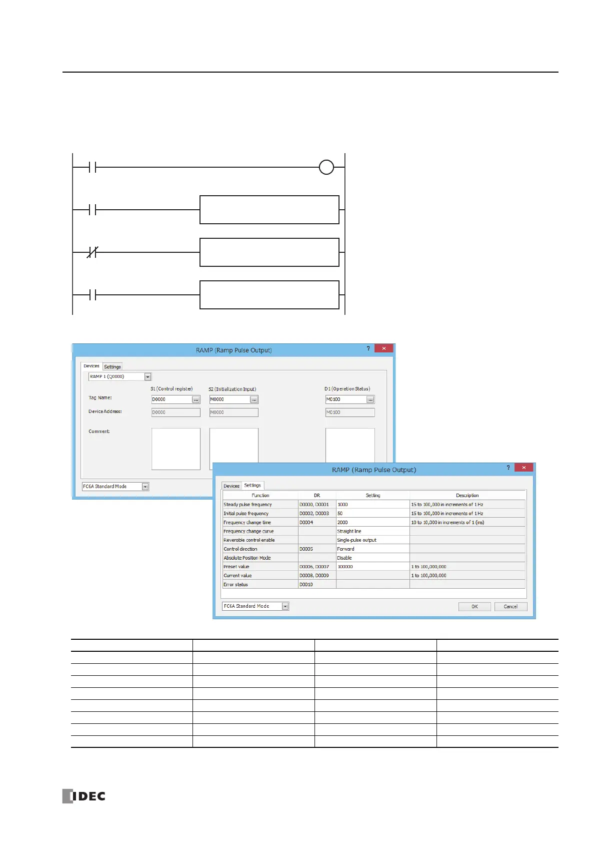
To output 100,000 pulses with the frequency change function (reversible control by single-pulse output) from Q0
When the RAMP instruction input (I0) changes from off to on, pulse output starts. When I1 is off, the reversible control signal (Q2)
turns off (forward).
When I1 is on, the reversible control signal (Q2) turns on (reverse).
Setting
Function Device Address Setting Value Details
Steady pulse frequency D0000, D0001 1000 1,000 Hz
Initial pulse frequency D0002, D0003 50 50 Hz
Frequency change time D0004 2000 2,000 ms
Frequency change curve — Straight line —
Reversible control enable — Single-pulse output —
Control direction D0005 Forward Forward=0
Absolute Position Mode — Disable —
Preset value D0006, D0007 100000 Preset value=100,000
M0000
M8120
I0001
I0000
REPD1 -
D0003
MOV(W) S1 -
0
REPD1 -
D0003
MOV(W) S1 -
1
D1
M0100
S2
M0000
RAMP
1
S1
D0000
I0001
When the RAMP instruction input (I0) turns on, pulse output
starts
When I1 is off, store 0 (forward) in control direction (D0003)
When I1 is on, store 1 (reverse) in control direction (D0003)
Turn on initialization input (M0000)

 Loading...