FC6A S
ERIES
MICROS
MART
L
ADDER
P
ROGRAMMING
M
ANUAL
FC9Y-B1726 18-49
18: P
ULSE
O
UTPUT
I
NSTRUCTIONS
3. S2 (source 2): Initialization Input
S2 specifies the initialization input.
When the initialization input S2 is turned on, the initial values configured in the WindLDR ARAMP (Advanced Ramp) dialog
box, on the Settings tab, are stored in the control registers. An external input or an internal relay can be specified.
When the initialization input is on, the initial values are stored in the data registers with each scan. (Even when the ARAMP
instruction is not executed (when not on), if the initialization input is turned on, the initial values are stored in the data
registers.) To only initialize the values one time, use the initialization input in combination with the SOTU (single output up)
instruction or the SOTD (single output down) instruction.
4. S3 (source 3): Interrupt Input
S3 specifies the interrupt input.
When the interrupt input changes from off to on, the pulse output process for the running step is aborted, and pulse output
starts with the settings for the step configured by the interrupt step number (10). When pulse output for the interrupt step
completes, pulse output starts for the next step according to the next step number (16).
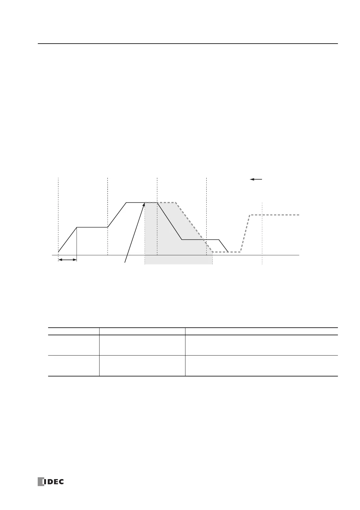
The following example shows the interrupt input turning on during step 2 when configured to output pulses in order from step 1
to step 18.
When the interrupt input turns on, step 2 which is currently outputting pulses is aborted, and pulse output starts from the step
number set as the interrupt step number (step 12). When step 12 completes, pulses are output for the next step according to
the set order of steps.
An external input or internal relay can be specified as the interrupt input.
The detection speed differs by the used device.
S3 is omitted if not using an interrupt input.
Notes:
• Do not use the same input or internal relay as the interrupt input signal for the ARAMP1, ARAMP2, ARAMP3, or ARAMP4 instructions.
• To use a high-speed interrupt input signal, set the relevant input to Normal Input under Special Inputs on Function Area Settings. Do
not use the input as interrupt input, catch input, high-speed counter, or frequency measurement.
• When using the high-speed interrupt input, ensure that no bounce occurs in the interrupt input.
• When the interrupt input is turned on, the control direction (forward or reverse) is unchanged regardless of the control direction of the
interrupted step.
Detection Speed Device Number Description
High-speed I0, I1, I3, I4, I6, I7
An interrupt is used to read the interrupt input.
The interrupt input can be read without being affected by the user
program scan.
Normal
Inputs except I0, I1, I3, I4, I6, and I7
and Internal relays
The information updated in the END processing is read as the interrupt
input.
It is affected by the user program scan.
Step 1 Step 2
Step 3 Step 4
Steady pulse frequency
Frequency
change time
Steady pulse frequency
Step 12 Step 13
Step 14
Step 3 to 11 are canceled
When the interrupt input is turned on,
step 2 processing is aborted and step 12 starts

 Loading...