18: P
ULSE
O
UTPUT
I
NSTRUCTIONS
18-50 FC6A S
ERIES
MICROS
MART
L
ADDER
P
ROGRAMMING
M
ANUAL
FC9Y-B1726
5. D1 (destination 1): Monitor Register
D1 specifies the first data register of the data registers to use with ARAMP1, ARAMP2, ARAMP3 or ARAMP4. Starting from the
specified data register, 11 consecutive data registers are used. Specify the first data register so that the device range is not
exceeded. The contents of the monitor registers are read-only.
*1 The upper and lower data registers change according to the 32-bit data storage method specified.
For details, see "32-bit Data Storage" on page 3-9.
Next step number
This register stores the number of the step to execute next.
If the next step is 0, pulse output ends after the currently executed step is complete.
Running step number
This register stores the number of the step that is currently being executed.
Steady pulse frequency monitor
This register stores the steady pulse frequency for the step that is currently being executed.
Frequency change time monitor
This register stores the frequency change time for the step that is currently being executed.
Set the time between 10 and 10,000 ms in increments of 1 ms. The first digit of the setting is handled as zero. For example,
if 144 is entered, the set value is handled as 140 ms.
Preset value monitor
This register stores the number of pulses to output for the running step.
Current value
This register stores the number of pulses that have been output for the step that is currently being executed. The current
value is updated when the ARAMP instruction is executed at each scan.
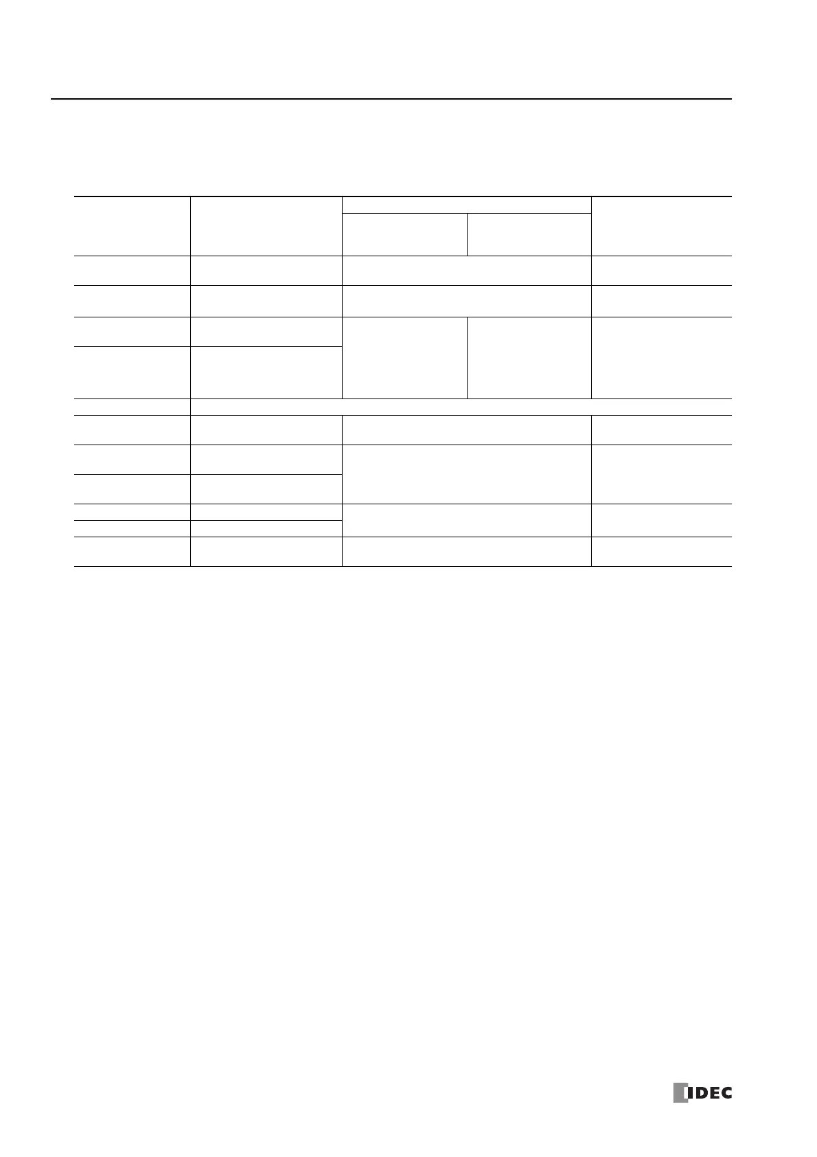
Address Function
Setting
Reference
All-in-One CPU
Module
CAN J1939 All-in-
One CPU Module/
Plus CPU Module
Starting number+0 Next step number 0 to 18
"Next step number" on
page 18-50
Starting number+1 Running step number 1 to 18
"Running step number" on
page 18-50
Starting number+2
Steady pulse frequency
monitor (high word)
*1
ARAMP1, ARAMP2:
15 to 100,000
(increments of 1 Hz)
ARAMP3, ARAMP4:
15 to 5,000
(increments of 1 Hz)
ARAMP1 to ARAMP4:
15 to 100,000
(increments of 1 Hz)
"Steady pulse frequency
monitor" on page 18-50
Starting number+3
Frequency change time
monitor (low word)
*1
Starting number+4 Reserved
Starting number+5
Frequency change time
monitor
10 to 10,000 (increments of 1 ms)
The first digit of the setting is handled as zero.
"Frequency change time
monitor" on page 18-50
Starting number+6
Preset value monitor
(high word)
*1
1 to 100,000,000 pulses
"Preset value monitor" on
page 18-50
Starting number+7
Preset value monitor
(low word)
*1
Starting number+8 Current value (high word)
*1
1 to 100,000,000 pulses
"Current value" on page
18-50
Starting number+9 Current value (low word)
*1
Starting number+10 Error status 0 to 9
"Error status" on page 18-
51

 Loading...