FC6A S
ERIES
MICROS
MART
L
ADDER
P
ROGRAMMING
M
ANUAL
FC9Y-B1726 18-59
18: P
ULSE
O
UTPUT
I
NSTRUCTIONS
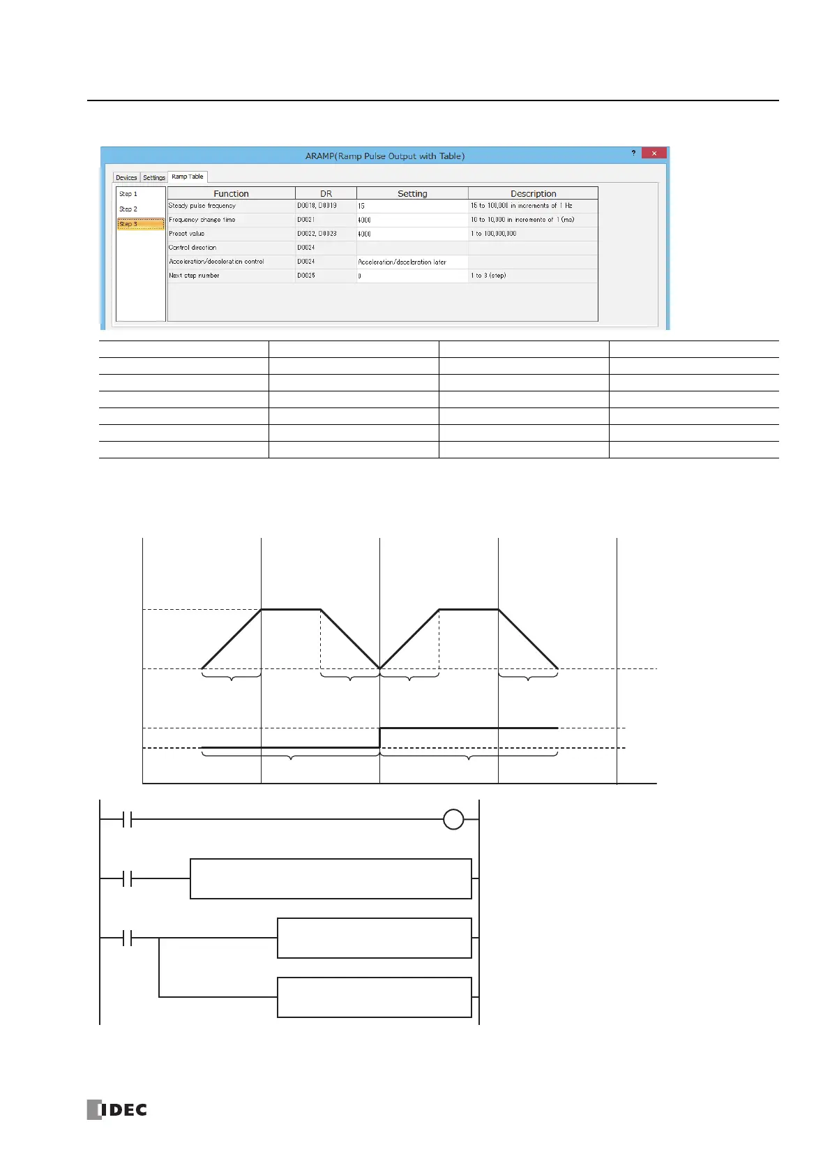
Step 3 settings
When outputting pulses as shown in the diagram below with the frequency change function (single-pulse output
reversible control enabled) using the following settings
Pulses are output from Q0 and the reversible control signal is output from Q2.
Function Device Address Setting Value Details
Steady pulse frequency D0018, D0019 15 15 Hz
Frequency change time D0021 4000 4,000 ms
Preset value D0022, D0023 4000 Preset value=4,000
Control direction D0024 — —
Acceleration/deceleration control D0024 Acceleration/deceleration later After=2
Next step number D0025 0 0=End output
Step
1
100 kHz
15 Hz
Q2
ON
OFF
Q0
Frequency
change time
3,000 ms
Frequency
change time
3,000 ms
Frequency
change time
3,000 ms
Frequency
change time
3,000 ms
Preset value 5,000 Preset value 5,000
1 kHz
Step
2
Preset value 5,000 Preset value 5,000
Step
3
Step 4
Forward Reverse
M0000
I0002
I0000
D2
M0050
D1
D0040
ARAMP
1
S3S2
M0000
S1
D0000
I0001
REPD1 -
D0002
MOV(W) S1 -
5000
REPD1 -
D0018
MOV(W) S1 -
5000
When the ARAMP instruction input (I0) turns on, pulse
output starts
When the MOV instruction input (I1) turns on, the steady
pulse frequencies for step 2 and step 4 (D0002, D0003 and
D0018, D0019) are changed to 5 kHz.
When I2 turns on, the initialization input (M0000) is turned
on and the ARAMP instruction control register values are
initialized

 Loading...