FC6A S
ERIES
MICROS
MART
L
ADDER
P
ROGRAMMING
M
ANUAL
FC9Y-B1726 18-85
18: P
ULSE
O
UTPUT
I
NSTRUCTIONS
Practical Examples
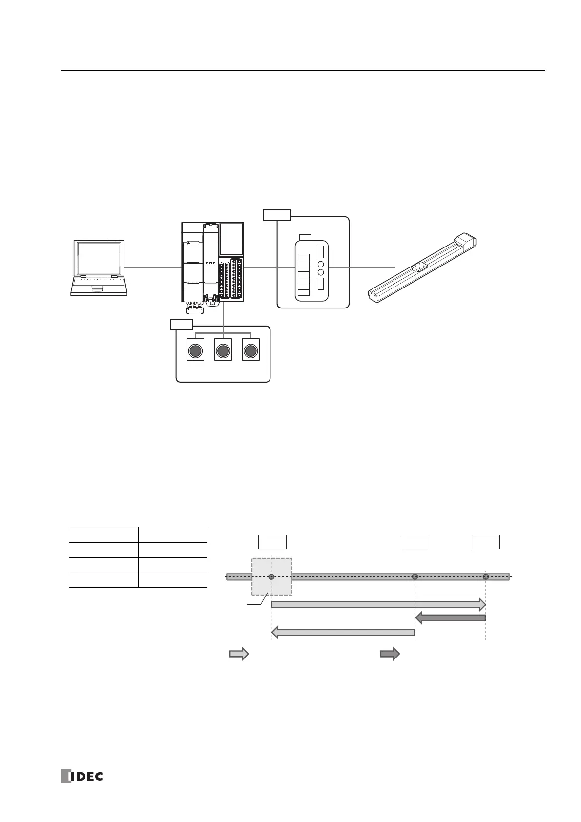
Example of Single Axis Control Using the RAMP Instruction
■ Application
Single axis electric slider
■ System configuration diagram
Electric slider specification is treated as 0.01 mm per pulse in this example.
To learn the actual travel distance of the electric slider that will be used, check the electric slider specifications (travel distance per
pulse).
■ Operation
When the stop movement switch is pressed for 3 seconds, ABS instruction will be executed to establish the origin.
When the start movement button is pressed, the electric slider moves as follows: Point A → Point C → Point B → Point A. The
electric slider stops when it reaches Point A the second time.
When the stop movement button is pressed, the moving electric slider stops.
When the zero return button is pressed, the electric slider returns to the origin (Point A) from the stopped position.
Movement from Point A to Point C and from Point B to Point A is executed with specify absolute position mode enabled.
Movement from Point C to Point B is executed with specify absolute position mode disabled.
If the frequency change curve is set to S-shaped curve, shocks and vibration are suppressed because the initial acceleration can
be reduced.
Position X (cm)
Distances in parentheses have been calculated at 0.01 mm per pulse.
Point A 0
Point B 20
Point C 30
Input
Output
WindLDR
FC6A Series MICROSmart
Motor driver
Stop
movement
button
Zero
return
button
Start
movement
button
Single axis electric slider
Example: 0.01 mm/pulse
Table
Specify absolute position mode: enabled Specify absolute position mode: disabled
30,000
(30 cm)
20,000
(20 cm)
0
(0 cm)
Point CPoint BPoint A

 Loading...