19: PID C
ONTROL
I
NSTRUCTION
19-20 FC6A S
ERIES
MICROS
MART
L
ADDER
P
ROGRAMMING
M
ANUAL
FC9Y-B1726
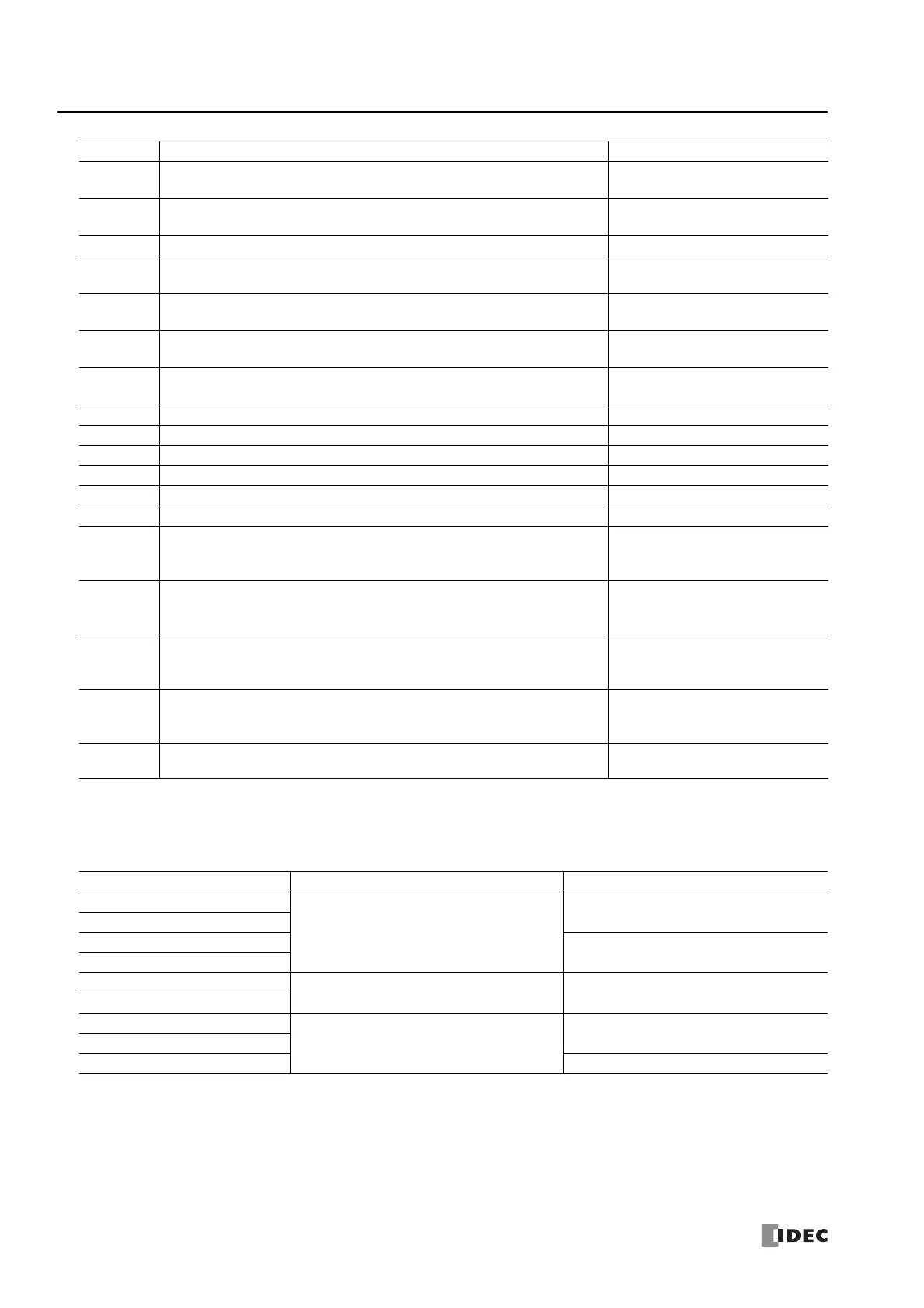
Alarm 3 value (S1+23)
Set the value that will be the trigger condition for the alarm. The value to set differs by the alarm type.
The content for the alarm value is as follows.
*1 No alarm action when the alarm value is 0.
S2: Initialization Input
When the initialize input is on, the control registers (data registers) are overwritten with the values configured on the WindLDR
input tab, control tab, and output tab. If you want the initialization to be performed just one time, please use a SOTU (shot up)
or a SOTD (shot down) instruction.
212
The action point for Alarm 5 with the set alarm value exceeded the process variable
minimum value or maximum value.
PID control control execution continues
213
The action point for Alarm 6 with the set alarm value exceeded the process variable
minimum value or maximum value.
PID control execution continues
214 to 219 — Reserved — —
220
The action point for Alarm 3 with the set hysteresis exceeded the process variable
minimum value or maximum value.
PID control execution continues
221
The action point for Alarm 4 with the set hysteresis exceeded the process variable
minimum value or maximum value.
PID control execution continues
222
The action point for Alarm 5 with the set hysteresis exceeded the process variable
minimum value or maximum value.
PID control execution continues
223
The action point for Alarm 6 with the set hysteresis exceeded the process variable
minimum value or maximum value.
PID control execution continues
224 to 229 — Reserved — —
230 The Alarm 3 delay time was set to a value of 10,001 or higher. PID control execution continues
231 The Alarm 4 delay time was set to a value of 10,001 or higher. PID control execution continues
232 The Alarm 5 delay time was set to a value of 10,001 or higher. PID control execution continues
233 The Alarm 6 delay time was set to a value of 10,001 or higher. PID control execution continues
234 to 239 — Reserved — —
240
When the Alarm 3 alarm type was set to the upper/lower limit alarm or the upper/
lower limit alarm with standby, the Alarm 3 hysteresis was set to a value that does not
satisfy hysteresis < alarm value.
PID control execution continues
241
When the Alarm 4 alarm type was set to the upper/lower limit alarm or the upper/
lower limit alarm with standby, the Alarm 4 hysteresis was set to a value that does not
satisfy hysteresis < alarm value.
PID control execution continues
242
When the Alarm 5 alarm type was set to the upper/lower limit alarm or the upper/
lower limit alarm with standby, the Alarm 5 hysteresis was set to a value that does not
satisfy hysteresis < alarm value.
PID control execution continues
243
When the Alarm 6 alarm type was set to the upper/lower limit alarm or the upper/
lower limit alarm with standby, the Alarm 6 hysteresis was set to a value that does not
satisfy hysteresis < alarm value.
PID control execution continues
244 to
65535
— Reserved — —
Status Code Status Description Status Classification
Alarm Type Alarm Value Range
Upper Limit Alarm
Set the deviation value from the set point.
-32,768 to 32,767
*1
Lower Limit Alarm
Upper/Lower Limit Alarm
0 to 65,535
*1
Upper/Lower Limit Range Alarm
Process High Alarm
Set the value where the alarm will operate as an
absolute value.
Minimum to maximum
Process Low Alarm
Upper Limit Alarm with Standby
Set the deviation value from the set point.
-32,768 to 32,767
*1
Lower Limit Alarm with Standby
Upper/Lower Limit Alarm with Standby 0 to 65,535
*1

 Loading...