19: PID C
ONTROL
I
NSTRUCTION
19-42 FC6A S
ERIES
MICROS
MART
L
ADDER
P
ROGRAMMING
M
ANUAL
FC9Y-B1726
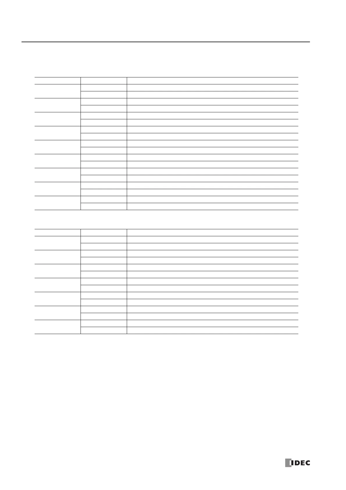
9. Status indicators
You can check the primary statuses for PID control with the colored indicators.
When a PIDA instruction is selected, the indicators in the following table are displayed.
When a PIDD instruction is selected, the indicators in the following table are displayed.
10. Trend graph
When a PIDA instruction is selected, you can monitor the values of the process variable (PV), set point (SP), manipulated
variable (MV), alarm 1 value (process high alarm), and alarm 2 value (process low alarm) with the trend graph.
When a PIDD instruction is selected, you can monitor the values of the process variable (PV), set point (SP), and output
manipulated variable (MV) with the trend graph.
Shown values, colors, maximum value, and minimum value can be changed in the PID Monitor Settings dialog box.
For details, see "PID Monitor Settings Dialog Box" on page 19-44.
Note: When plots on the trend graph reach the right edge of the graph, the center of the graph moves to the left edge and the new log information
is displayed from the center of the graph. You can check the past log information by moving the scrollbar. The log information retains a maximum of
10,000 items of information. When the log information has reached 10,000 items of information, the log information is deleted from the oldest
items, and the new log information is recorded. The log information displayed on the trend graph is deleted when the dialog box is closed or when
the PIDA/PIDD instruction being monitored is changed.
Indicator Name Background Color Status
PID
Gray PID control stopped
Green PID control is executed
AT
Gray AT stopped
Green AT is being executed
MANUAL
Gray Auto mode
Green Manual mode
A1
Gray Normal operation
Red Alarm 1 output is ON
A2
Gray Normal operation
Red Alarm 2 output is ON
A3
Gray Normal operation
Red Alarm 3 output is ON
A4
Gray Normal operation
Red Alarm 4 output is ON
A5
Gray Normal operation
Red Alarm 5 output is ON
A6
Gray Normal operation
Red Alarm 6 output is ON
Indicator Name Background Color Status
MANUAL
Gray Other mode
Green Manual mode
AUTO
Gray Other mode
Green Auto mode
CASCADE
Gray Other mode
Green Cascade control mode
PV Tracking
Gray PV tracking disabled
Green PV tracking enabled
Kp Dependent
Gray Kp independent
Green Kp dependent
Kd
Gray Derivative action disabled
Green Derivative action enabled
Kd Decay
Gray Derivative decay disabled
Green Derivative decay enabled

 Loading...