FC6A S
ERIES
MICROS
MART
L
ADDER
P
ROGRAMMING
M
ANUAL
FC9Y-B1726 27-3
27: F
LOW
C
ALCULATION
I
NSTRUCTIONS
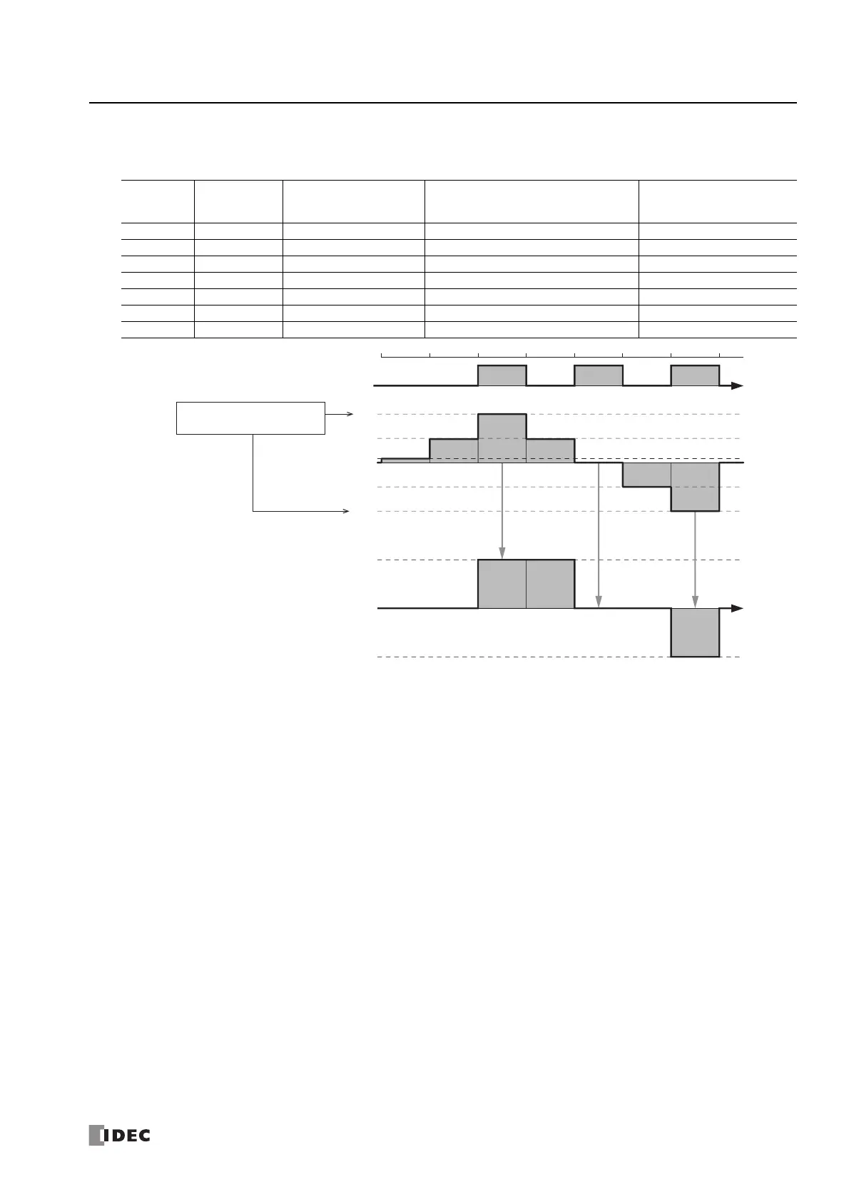
Example 1: When the dead band is enabled
When the dead band (S2+6, S2+7) is 100 and initial value of the output value (dead band) (D1+2, D1+3) is 0, the operation
in regard to the output value (D1+0, D1+1) is as follows.
Cycle
Output Value
(D1+0, D1+1)
Output Value (dead
band)
(D1+2, D1+3)
Absolute Value of the Difference
between the Output Value and the
Output Value (dead band) (D1+4, D1+5)
Output Value (dead band)
Change Notification
(D2+0)
1st scan 10 0 10 OFF
2nd scan 50 0 50 OFF
3rd scan 100 100 100 ON
4th scan 50 100 50 OFF
5th scan 0 0 100 ON
6th scan -50 0 50 OFF
7th scan -100 -100 100 ON
Output value (dead band) change notification
(D2+0)
100
ON
OFF
Output value
(D1+0, D1+1)
10
50
-100
-100
Output value (dead band)
(D1+2, D1+3)
-50
Initial value 0
100
Dead band (S2+6, S2+7)
=100
(1) (1)(1)
(2)
(2)(2)
(3) (3) (3)
(1)
1st scan 2nd scan 3rd scan 4th scan 5th scan 6th scan 7th scan
(1) Since the absolute value of the difference (D1+4, D1+5) between the output value and the output value (dead band) is
less than the dead band, the output value (D1+0, D1+1) is not stored in the output value (dead band) (D1+2, D1+3).
(2)
Since the absolute value of the difference (D1+4, D1+5) between the output value and the output value (dead band) is greater
than or equal to the dead band, the output value (D1+0, D1+1) is stored in the output value (dead band) (D1+2, D1+3).
(3) Output value (dead band) change notification (D2+0) turns on for one scan when (2) occurs.

 Loading...