27: F
LOW
C
ALCULATION
I
NSTRUCTIONS
27-4 FC6A S
ERIES
MICROS
MART
L
ADDER
P
ROGRAMMING
M
ANUAL
FC9Y-B1726
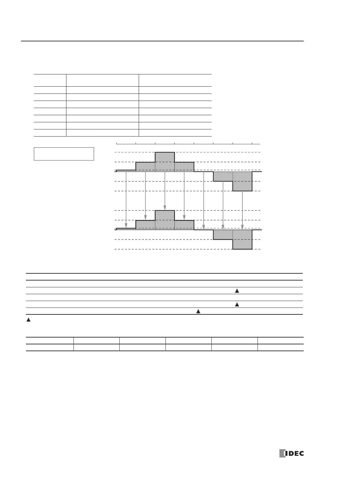
Example 2: When the dead band is disabled
When the dead band (S2+6, S2+7) is 0 and initial value of the output value (dead band) (D1+2, D1+3) is 0, the output
value (D1+0, D1+1) is stored in the output value (dead band) (D1+2, D1+3) with each scan.
Valid Devices
Special data registers cannot be designated as S2 and D1. Special internal relays cannot be designated as D2.
Data Types
The data type setting is only reflected in the input value.
Cycle Output Value (D1+0, D1+1)
Output Value (dead band)
(D1+2, D1+3)
1st scan 10 10
2nd scan 50 50
3rd scan 100 100
4th scan 50 50
5th scan 0 0
6th scan -50 -50
7th scan -100 -100
Device Function I Q M R T C D P Constant Repeat
S1 (Source 1) Input value —————— X — — —
S2 (Source 2) Control register — — — — — — — — —
S3 (Source 3) Initialization input X — X — — — — — — —
D1 (Destination 1) Output register —————— — — —
D2 (Destination 2) Output relay — X — — — — — — —
Data Type W (word) I (integer) D (double word) L (long) F (float)
Specifiable Yes Yes — — —
100
10
50
-100
-50
100
10
50
-100
-50
Output value
(D1+0, D1+1)
Output value (dead band)
(D1+2, D1+3)
Dead band (S2+6, S2+7)
=0
1st scan 2nd scan 3rd scan 4th scan 5th scan 6th scan 7th scan

 Loading...