12
Step 1
Step 2
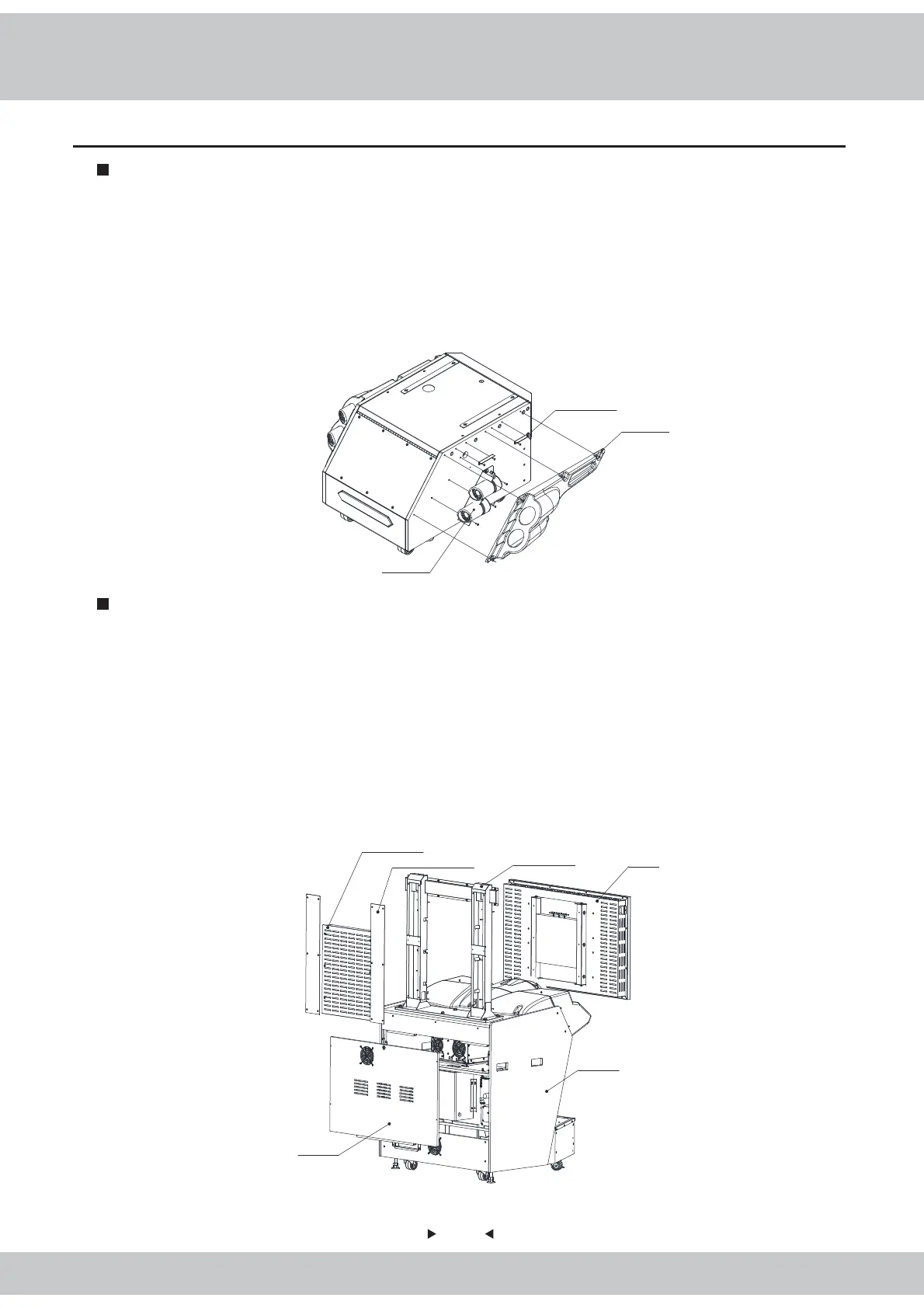
2.6 Install Direction
Reinforced plastic sheet metal of exhaust-pipe
Right-side plastic of exhaust pipe
Right-side assembly of exhaust pipe
1. First of all, the two pieces of reinforced-plastic sheet metals of exhaust-pipe are fixed to the base
with the large cross-head flat screws (black-plated).
2. After the right-side assembly of the exhaust pipe is fixed to the base with 3 large cross-head flat
screws M4 * 12 (black-plated), then the wires on the exhaust pipe are connected properly.
3. The right-side plastic of the exhaust pipe is fixed to the base with 5 flat-head screws M4 x 25
(black-plated).
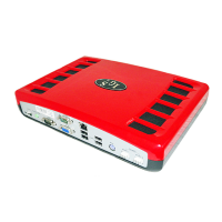
1. After the display assembly is taken out of the packaging box, the display service panel and the
display cover-plate are removed respectively, then the display is removed to have the display
separated from the display supporting frame.
2. First of all, use the hexagonal screws M8 * 50 (black-plated), spring washers M8 (black-plated)
and flat gaskets φ8*φ22*2.0 (black-plated) to install the display supporting frame to the host machine;
Reuse the screws removed from the display to install the display to the display supporting frame.
3. After 4 screws on the back service-door are removed, use the same-size key to open the door in
order to have the connecting wires connected properly.
Display
Display supporting
frame
Display deck-plate
Display back service-door
Host machine
Display service-panel