Page 22 Manual
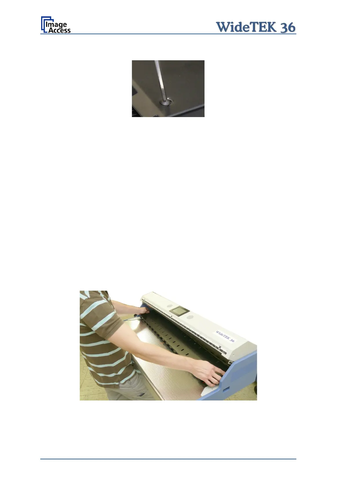
With the 2.5 mm Allen wrench loosen the two Allen head screws slightly.
Picture 5: Allen head screw in slot hole
The screws are mounted in slot holes. This allows moving the metal ballast.
If the metal ballast is moved all the way to the front or outer edge of the guide plate, the
contact pressure is minimal.
If it is pushed back or towards the middle, the contact pressure increases.
The default position of the Allen head screws is in the middle of the slot hole of the middle
guide plate. This position achieves a moderate contact pressure.
Older units may have been set to the maximum pressure. After the Allen head screws are
loosened the metal ballast at the bottom side can be moved.
Refasten the Allen head screws after modifying the position of the metal ballast.
If the Allen head screws do not move easily, the self locking nuts on the bottom side of the
middle guide plate could be too tight. If this is the case, remove the guide plate from the
scanner.
Two gaps at the right and left side of the top end (in paper transport direction) allow lifting
up the guide plate. First, lift up the guide plate at the front side and then push it slightly in
the paper transport direction. Finally, lift the rear end of the guide plate and move the
guide plate out of its position.
Picture 6: Removing the middle guide plate