Page 28 Manual
A.13 Connecting an External Monitor
The external monitor will be connected to the VGA connector of the mainboard inside the
scanner. To locate the VGA connector it is necessary to remove the middle guide plate at
first.
Open the upper part of the scanner by releasing the snap locks (see Picture 9) at the left
and right side of the housing.
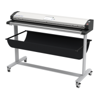
As described in chapter A.11 remove the middle guide plate. Now the compensators are
visible. The VGA connector position can be found between the first and the second
compensator, counted from the right side of the scanner.
Picture 16: Position of VGA connector
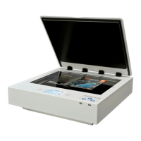
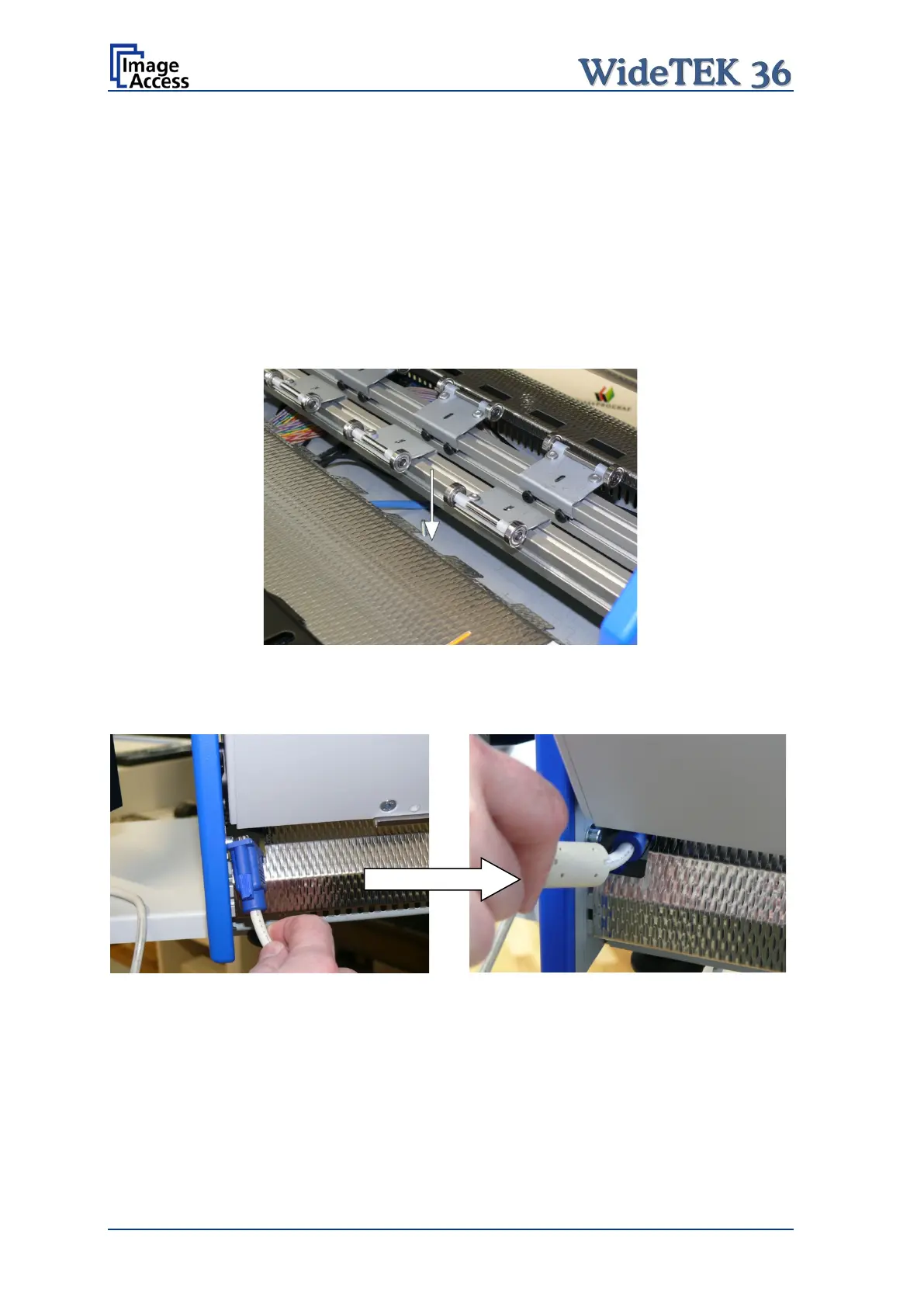
At the right side of the back of the scanner – seen from operators’ position – a gap in the
rear guide plate can be found. Guide the signal cable of the monitor through this gap.
Picture 17: VGA connector beside gap
Picture 18: Guiding into the scanner