SD1 Series Inverters Communication Protocol
-116-
-2V~-6V; it is logic "0".
485+ on the terminal board corresponds to A and 485- to B.
Communication baud rate means the binary bit number in one second. The unit is bit/s (bps).
The higher the baud rate is, the quicker the transmission speed is and the weaker the
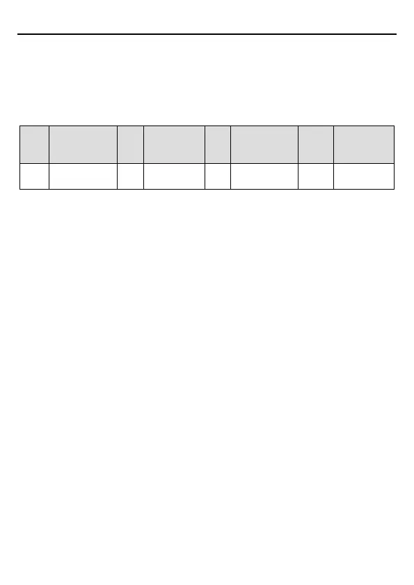
anti-interference is. If the twisted pairs of 0.56mm (24AWG) are applied as the communication
cables, the max. transmission distance is as follows:
Baud
rate
transmission
Baud
rate
Max.
transmission
distance
Baud
rate
transmission
Baud
rate
Max.
transmission
distance
1800m
1200m
800m)
600m
It is recommended to use shielded cables and make the shield layer as the grounding wires
during RS485 remote communication.
In cases with less devices and shorter distances, it is recommended to use 120Ω terminal
resistor as the performance will be weakened if the distance increases even though the
network can perform well without a load resistor.
7.2.1.1 When one inverter is used
Figure 7-1 is the site Modbus connection figure of single inverter and PC. Generally, the
computer does not have RS485 interface, the RS232 or USB interface of the computer should
be converted into RS485 by a converter. Connect the A terminal of RS485 to the 485+ terminal
of the inverter and B to the 485- terminal. It is recommended to use shielded twisted pairs.
When applying RS232-RS485 converter, if the RS232 interface of the computer is connected
to the RS232 interface of the converter, the wire length should be as short as possible,
typically less than 15m. It is recommended to connect the RS232-RS485 converter to the
computer directly. If using USB-RS485 converter, the wire should be as short as possible, too.
Select the right interface to the upper monitor of the computer (select the interface of
RS232-RS485 converter, such as COM1) after the wiring and set the basic parameters such
as communication baud rate and digital check bit to the same as the inverter.