SD1 Series Inverters Installation Guidelines
-20-
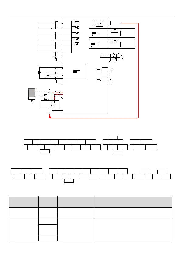
COM
GND
Multi-function input terminal 1
Multi-function input terminal 2
Multi-function input terminal 4
High speed pulse input collector
Multi-function input terminal 3
Open collector input optional
Y1 output
Analog output
Analog output
Relay 1 output
Relay 2 output
Shield layer
Twisted pair
PE
PE
S2
H1
Safety switch
Safety controller
Open circuit
Safety state feedback
Safety input
S1
H2
+ 24V
PE
PE
0-10V/0-20mA
0-10V/0-20mA
RS485
communication
485+
485-
RO1A
RO1B
RO1C
RO2A
RO2B
RO2C
AO1
GND
AO1
AO2
GND
Y1
COM
S1
S2
S3
S4
HDI
PW
+24V
+10V
AI2
AI3
AI2
V
I
AO2
I
Figure 3-10 Wiring of control circuit for inverters ≥ 1.5kW (3PH 230V) & ≥ 4kW (3PH 400V)
3.2.5 Control circuit terminals
S1 S2
S3 S4
HDI AI2 AI3
+10V
+24V PW COM COM Y1 AO1 485+ 485-
+24V H1
+24V H2
RO1B
RO1C
RO1A RO1C
Figure 3-11 Connection terminal diagram for inverters ≤ 2.2 kW (1PH 230V, 3PH 400V) & ≤
0.75kW (3PH 230V)
S1 S2 S3
S4 HDI Y1 AI2 AI3
+24V PW COM COM GND AO1 AO2 485+
RO1A RO1B RO1C
RO2A RO2B
RO2C
+10V
485- +24V
H1 +24V H2
Figure 3-12 Connection terminal diagram for inverters ≥ 1.5kW (3PH 230V) & ≥ 4kW (3PH
400V)
Type
Technical specifications
Communication
485
485 communication interfaces
Digital
input/output
Digital input
1. Internal impedance: 3.3kΩ
2. 12~30V voltage input is available
3. The terminal is the dual-
terminal