SD1 Series Inverters Installation Guidelines
-24-
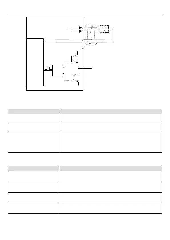
Control
circuit
+24V
Switch, relay, etc.
UDC+
UDC-
Drive
circuit
PWM+
PWM-
U/V/W
H1
H2
Note: The contact of safety switch must be
opened/closed within 250ms; the cable between the
VFD and safety switch should be no longer than
25m.
COM
Figure 3-16 STO function schematic
3.3.1 Logic table for STO function
Input states and corresponding faults of STO function:
H1, H2 opens simultaneously Trigger STO function, the drive can't operate normally
H1, H2 closes simultaneously
Don't trigger STO function, the drive can operate normally
Either H1 or H2 opens or
closes
Trigger STL1/STL2/STL3 fault, fault code:
38: Safety circuit of channel 1 is abnormal (STL1)
39: Safety circuit of channel 2 is abnormal (STL2)
40: Internal circuit is abnormal (STL3)
3.3.2 Description of STO channel delay
STO channel trigger and indication delay time:
1
2
STO fault: STL1
Trigger delay < 10ms
Indication delay < 280ms
STO fault: STL2
Trigger delay < 10ms
STO fault: STL3
Trigger delay < 10ms
Indication delay < 280ms
STO fault: STO
Trigger delay < 10ms
1: STO trigger delay: Time interval between trigger the STO function and switching off the