SD1 Series Inverters Optional Peripheral Accessories
-161-
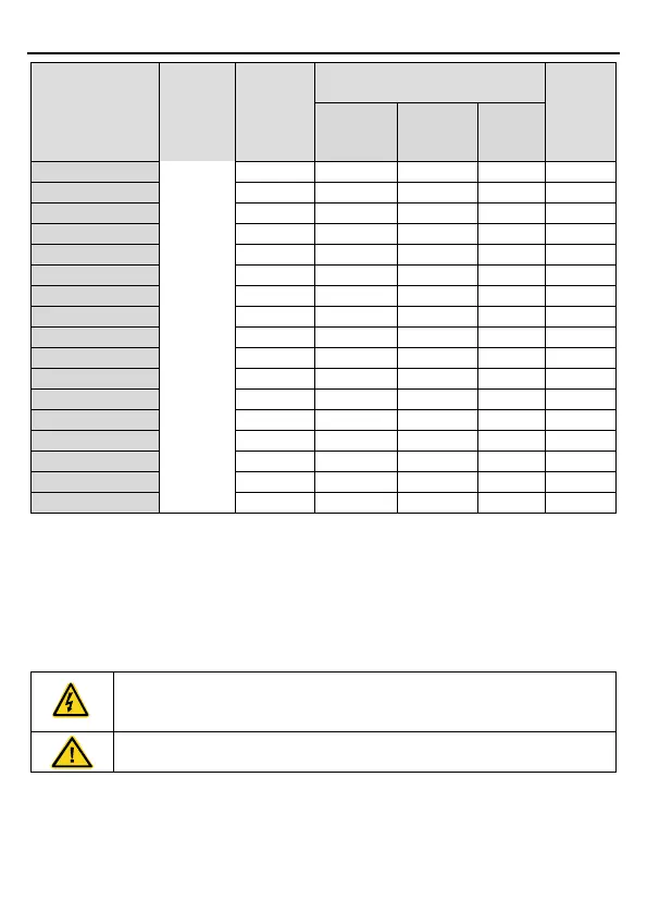
Model
Type of
braking
unit
resistor at
100% of
braking
Consumed power of the braking
resistor (kW)
Min.
braking
resistor
(Ω)
10%
braking
50%
braking
80%
braking
Note:
Select the resistor and power of the braking unit according to the data our company
provided.
The braking resistor may increase the braking torque of the inverter. The resistor power in
the above table is designed on 100% braking torque and 10% braking usage ratio. If the
users need more braking torque, the braking resistor can decrease properly, and the power
needs to be magnified.
Never use a braking resistor with a resistance below the minimum value
specified for the drive. The drive and the internal chopper are not able to
handle the overcurrent caused by the low resistance.
Increase the power of the braking resistor properly in the frequent braking
situation (the frequency usage ratio is more than 10%).
C.7.2 braking resistor installation
Braking resistor cables need to be shielded cables.
Install all resistors in a place where they will cool.