SD1 Series Inverters Communication Protocol
-121-
7.2.3 Ascii mode
Coding
system
Communication protocol belongs to hexadecimal system. The meaning of message
character in ASCII: "0"…"9", "A"…"F", each hex is
message corresponds to the character.
Data
format
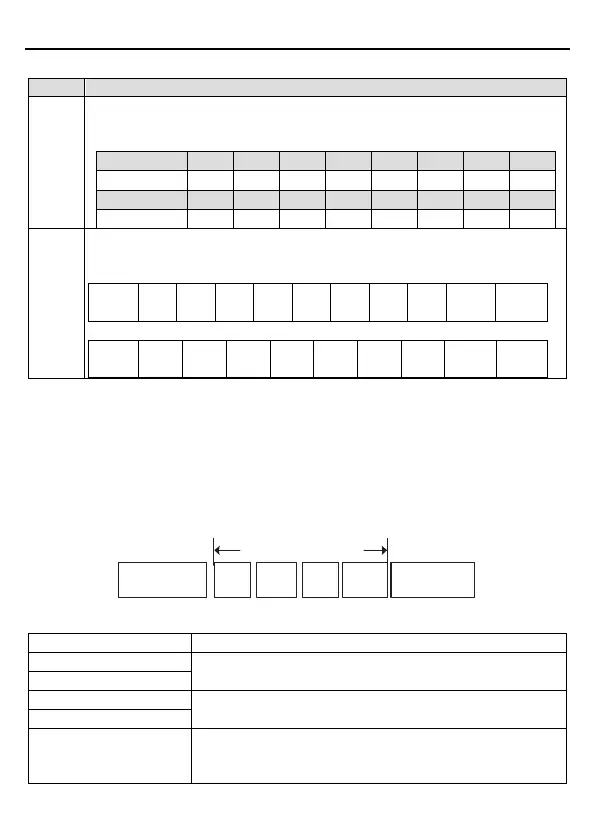
Starting bit, 7/8 data bit, check bit and stop bit. The data formats are listed as
below:
11-bit character frame:
BIT1 BIT2 BIT3
BIT4
BIT5 BIT6 BIT7 BIT8
Check
Stop bit
10-bit character frame:
BIT1 BIT2 BIT3 BIT4 BIT5 BIT6 BIT7
Check
Stop bit
In ASCII mode, the frame header is ":" ("0*3A"), frame end is "CRLF" ("0*0D" "0*0A") by
default. In ASCII mode, all the data bytes, except for the frame header and frame end, are
transmitted in ASCII code mode, in which four high bit groups will be sent out first and then,
four low bit groups will be sent out. In ASCII mode, the data length is 8 bit. As for 'A'~'F', its
capital letters are adopted for ASCII code. The data now adopts LRC checkout which covers
slave address to data information. The checksum equals to the complement of the character
sum of all the participated checkout data.
ASCII data frame format
Modbus message
Starting character:
“0x3A”
Slave
address
Function
code
Data
Checkout
Ending character:
“0*0D”“0*0A”
Standard structure of ASCII frame:
Communication address:
8-bit address is formed by the combination of two ASCII codes
Function code:
8-bit address is formed by the combination of two ASCII codes
DATA (N-1)
…
Data content:
nx8-bit data content is formed by combination of 2n (n≤16)