SD1 Series Inverters Installation Guidelines
-19-
and connect the 3PH input cable to the terminals R, S, and T, and fasten them up.
2. Connect the ground wire of the motor cable to the ground terminal of the inverter and
connect the 3PH motor cable to the terminals U, V, and W, and fasten them up.
3. Connect the braking resistor and other accessories that are equipped with cables to the
specified positions.
4. Fasten all the cables outside of the inverter mechanically, if possible.
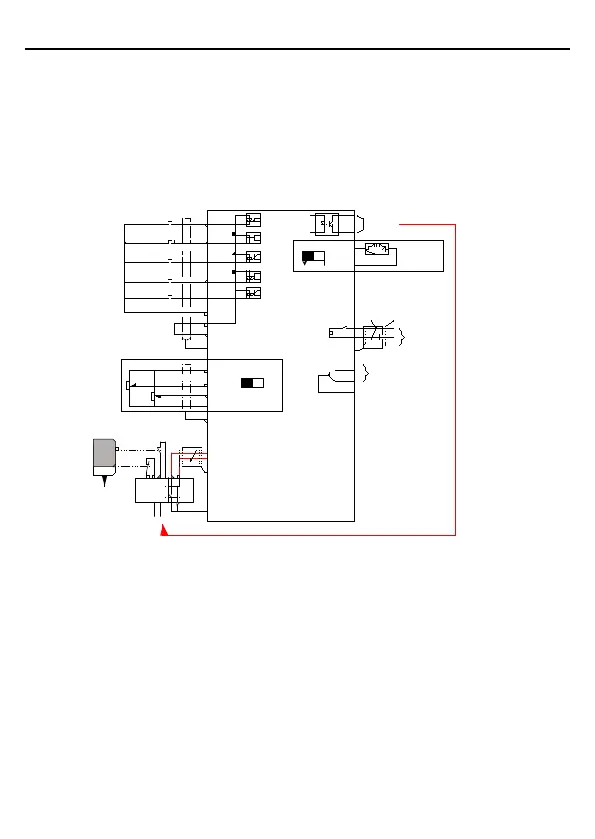
3.2.4 Wiring of control circuit
COM
COM
Multi-function input terminal 1
Multi-function input terminal 2
Multi-function input terminal 4
High speed pulse input collector
Multi-function input terminal 3
Open collector input optional
Y1 output
Analog output
Relay 1 output
Shield layer
Twisted pair
PE
PE
S2
H1
Safety switch
Safety controller
Open circuit
Safety state feedback
Safety input
S1
H2
+ 24V
PE
PE
0-10V/0-20mA
RS485
communication
485+
485-
RO1A
RO1B
RO1C
AO1
COM
AO1
Y1
COM
S1
S2
S3
S4
HDI
PW
+24V
+10V
AI2
AI3
AI2
V
I
Figure 3-9 Wiring of control circuit for inverters ≤ 2.2 kW (1PH 230V, 3PH 400V) & ≤ 0.75kW
(3PH 230V)