SD1 Series Inverters Product Overview
-12-
Model
Voltage
degree
Rated
power (kW)
Rated input
current (A)
current (A)
STO
function
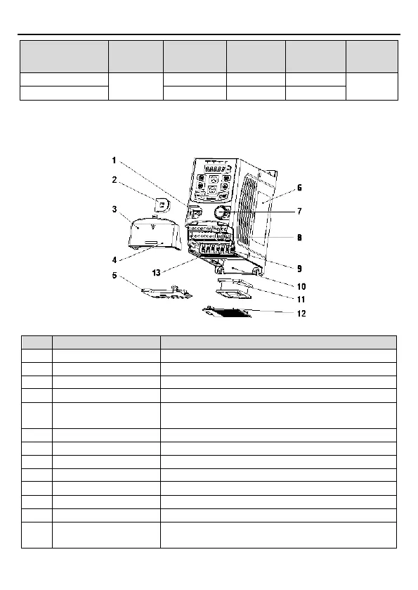
2.8 Structure Diagram
The following figure shows the structure of the inverter (3PH 400V, ≤2.2kW) (using the 0.75kW
inverter model as the example).
Figure 2-3 Product structure (3PH 400V, ≤2.2kW)
Connect the external keypad
Protect the external keypad port
Protect the internal parts and components
Hole for the sliding cover
5 Gland plate
Protect the inner components and fix the cables of the
main circuit
See section 2.5 "Product Nameplate" for details.
Refer to Chapter 4 "Keypad Operation".
See Chapter 3 "Installation Guidelines" for details.
See Chapter 3 "Installation Guidelines" for details.
Fix the fan cover and fan.
See Chapter 6 "Fault Tracking" for details.
13 Bar code
The same as the bar code on the name plate
Note: The bar code is on the middle shell which is under