SD1 Series Inverters Communication Protocol
-130-
MSB—00~ffH; LSB—00~ffH. The MSB is the group number before the radix point of the
function code and the LSB is the number after the radix point, but both the MSB and the LSB
should be converted into hex. For example, P05.05, the group number before the radix point
of the function code is 05, then the MSB of the parameter is 05, the number after the radix
point 05, then the LSB the parameter is 05, then the function code address is 0505H and the
parameter address of P10.01 is 0A01H.
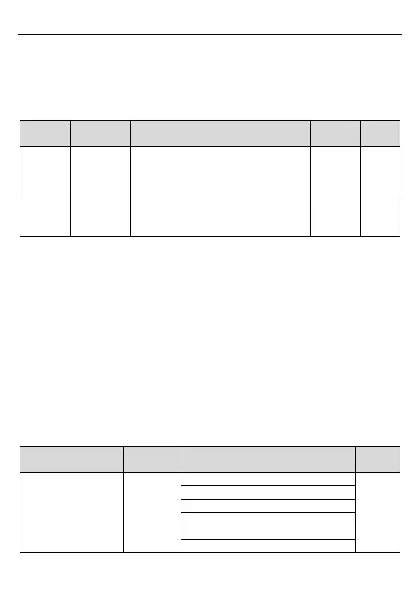
Function
Name Description Default Modify
P10.00
Simple PLC
mode
0: Stop after running once.
1: Keep running in the final value after
running once.
0 ○
P10.01
Simple PLC
memory
-off
after power-off
0 ○
Note: P29 group is the factory parameter which cannot be read or changed. Some parameters
cannot be changed when the inverter is in the running state and some parameters cannot be
changed in any state. The setting range, unit and relative instructions should be paid attention
to when modifying the function code parameters.
Besides, EEPROM is written frequently, which may shorten the usage time of EEPROM. For
users, some functions are not necessary to be stocked on the communication mode. The
needs can be met on by changing the value in RAM. Changing the high bit of the function code
from 0 to 1 can also realize the function. For example, the function code P00.07 is not written
into EEPROM. Only by changing the value in RAM can set the address to 8007H. This
address can only be used in writing RAM other than reading. If it is used to read, it is an invalid
address.
7.4.2 Description of other function addresses in Modbus
The master can operate on the parameters of the inverter as well as control the inverter, such
as running or stopping and monitoring the working state of the inverter.
Below is the parameter table of other functions.
Function instruction
Data meaning instruction
Communication control
command
2000H
R/W