SD1 Series Inverters Installation Guidelines
-23-
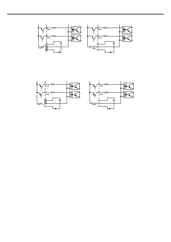
according to the used power supply.
S1
S2
COM
PW
+ 24V
COM
+24V
S1
S2
COM
PW
+ 24V
COM
+24V
+ 24V
Internal power supply
External power supply
Figure 3-14 NPN modes
If the signal is from PNP transistor, set the Jumper link as below according to the used power
supply.
S1
S2
COM
PW
+ 24V
COM
+24V
S1
S2
COM
PW
+ 24V
COM
+
24V
Internal power supply
External power supply
Figure 3-15 PNP modes
3.3 Overview of STO Function
Reference standards: IEC 61508-1, IEC 61508-2, IEC 61508-3, IEC 61508-4, IEC 62061, ISO
13849-1, IEC 61800-5-2.
The STO function can be used where main power of the drive is on to prevent unexpected
start. The function cuts off the drive signal to disable the drive output, thus preventing motor
from unexpected start (refer to below figure). After enabling STO function, short-time
operations (like non-electrical cleaning-up in lathe industry) and/or maintenance on
non-electrical parts can be conducted.