SD1 Series Inverters Communication Protocol
-134-
The encoding rules for device codes (corresponds to identifying code 2103H of the inverter)
01
Vector
06 SD1 Vector inverter
Note: The code is consisted of 16 bit which is high 8 bits and low 8 bits. High 8 bits mean the
motor type series and low 8 bits mean the derived motor types of the series. For example,
0110H means SD1 vector inverters.
7.4.3 Fieldbus scale
The communication data is expressed by hex in actual application and there is no radix point
in hex. For example, 50.12Hz cannot be expressed by hex so 50.12 can be magnified by 100
times into 5012, so hex 1394H can be used to express 50.12.
A non-integer can be timed by a multiple to get an integer and the integer can be called
fieldbus ratio values.
The fieldbus ratio values are referred to the radix point of the setting range or default value in
the function parameter list. If there are figures behind the radix point (n=1), then the fieldbus
ratio value m is 10
n
. Take the table as the example:
Name Description Default Modify
P01.20
0.0~3600.0s (valid when P01.19 is
2)
0.0s ○
P01.21 Restart after power off
0 ○
If there is one figure behind the radix point in the setting range or the default value, then the
fieldbus ratio value is 10. If the data received by the upper monitor is 50, then the "hibernation
restore delay time" is 5.0 (5.0=50÷10).
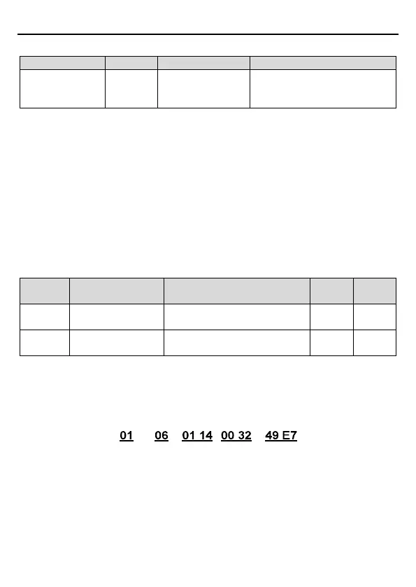
If Modbus communication is used to control the hibernation restore delay time as 5.0s. Firstly,
5.0 can be magnified by 10 times to integer 50 (32H) and then this data can be sent.
VFD
address
Write
command
Parameters
address
Data number CRC check
After the inverter receives the command, it will change 50 into 5 according to the fieldbus ratio
value and then set the hibernation restore delay time as 5s.
Another example, after the upper monitor sends the command of reading the parameter of
hibernation restore delay time, if the response message of the inverter is as following: