SD1 Series Inverters Installation Guidelines
-22-
Type
Technical specifications
3. Voltage or current input can be set by dip
switch.
4. Resolution: T
he minimum AI2/AI3 is
10mV/20mV when 10V corresponds to
50Hz.
AO1
Analog output
1. Output range: 0~10V voltage or 0~20mA
current.
2. Voltage or current output is set by
jumpers or toggle switch.
3. Error ±1%, 25°C.
4. There is only one AO1 for inverters
AO2
Relay output
1. Contact capacity: 3A/AC250V,
1A/DC30V.
2. Please note that it should not be used as
high frequency switch output.
3. There is only one relay output for
inverters ≤2.2kW.
RO1C
Relay 1 common
RO2C
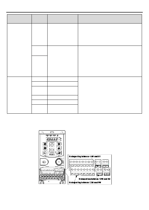
3.2.6 Input/output signal connection figure
Use Jumper link to set NPN mode or PNP mode and the internal or external power supply. The
default setting is the PNP internal mode.
Fi
gure 3-13 Jumper link
If the signal is from NPN transistor, set the Jumper link between +24V and PW as below