SD1 Series Inverters Product Overview
-13-
Note: In above figure, the screws at 4 and 10 are provided with packaging and specific
installation depends on the requirements of customers.
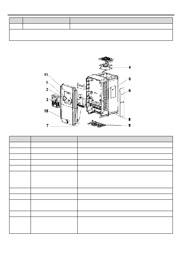
The following figure shows the structure of the inverter (3PH 400V, ≥4kW) (using the 4kW
inverter model as the example).
Figure 2-3 Product structure (Three phase 400V, ≥4kW)
Connect the external keypad
Protect the internal parts and components
Refer to Chapter 4 "Keypad Operation".
See Chapter 6 "Fault Tracking" for details
See section 2.5 "Product Nameplate" for details.
6
Cover for the heat
emission hole
Optional, enhancement of the protective degree. It
is necessary to derate the inverter
because the
internal temperature is increasing
See Chapter 3 "Installation Guidelines" for details.
See Chapter 3 "Installation Guidelines" for details.
9
The cable entry of the
main circuit
Fix the cables
Refer to section 2.6 "Mode Code".
11 Bar code
The same as the bar code on the name plate
Note:
The bar code is on the middle shell which is
under the cover