SD1 Series Inverters Communication Protocol
-128-
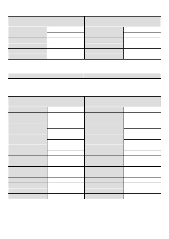
ASCII master command message (the
command sent by the master to inverter)
ASCII slave response message (the
message sent by the inverter to master)
Low bit of data content
Low bit of data content
7.3.2.3 Command code 08H (0000 1000), diagnosis
Meaning of sub function code:
Return inquiry message data
For instance: carry out circuit detection on drive address 01H, the content of inquiry message
word string is the same with response message word string, its format is listed as below:
7.3.2.4 Command code 10H, continuous writing
Command code 10H means the master write data to the inverter, the number of data being
written is determined by the command "data number", the max. number of continuous writing
is 16 words.
ASCII master command message (the
command sent by the master to inverter)
ASCII slave response message (the
message sent by the inverter to master)
ADDR
ADDR
CMD
CMD
High bit of write data
High bit of write data
Low bit of write data
Low bit of write data
High bit of data
High bit of data
Low bit of data content
Low bit of data content